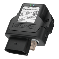
Figure 14. Individual wires open
Table 17. Start cable for main plug connector, individual wires open
Designation Color Description
Terminal 31 / ground Green Power supply
Analog input 1 Yellow I/O input
Analog input 2 Gray I/O input
Not used
Digital output Blue I/O output
Terminal 15 Red Input (ignition signal)
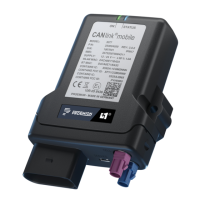
Figure 15. Power connector, low voltage coupling
Table 18. Start cable for main plug connector, power supply cable
Pi
n
Designation Color Description
1 Terminal 31 / ground Green Power supply
2 Terminal 30 / VCC White Power supply
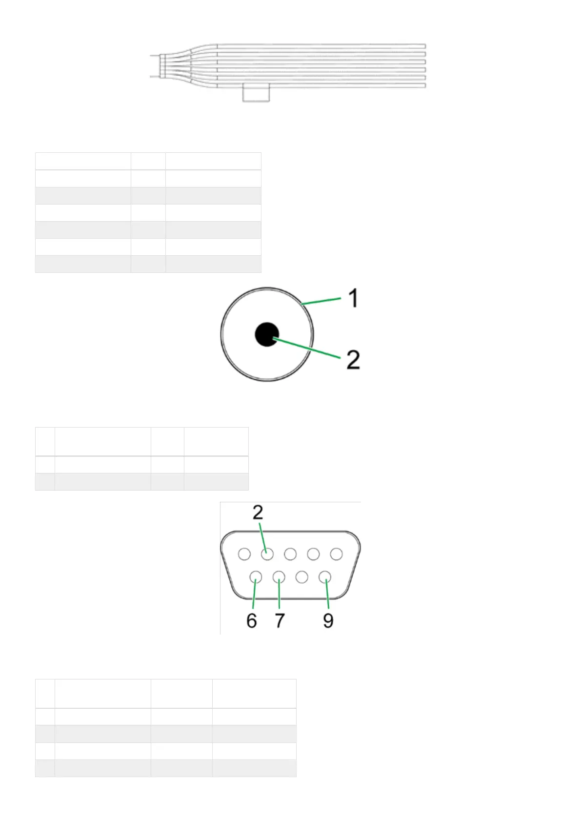
Figure 16. D-sub connector, female, 9-pin (CAN1)
Table 19. Start cable for main plug connector, D-Sub connector (CAN1)
Pi
n
Designation Color Description
1 not assigned - -
2 CAN1-Low Brown-green CAN, bidirectional
4 not assigned - -
5 not assigned - -
CANlink wireless 4000 Device Manual
 Loading...