PROFIBUS DP Interface 6
Next_Dout_Buffer_Cmd. If the user is supposed to enlarge the output data
buffer after the Chk_Cfg telegram, the user must delete this deviation in the
'N' buffer himself (possible only during the start-up phase in the WAIT-CFG
state).
If ‘Diag.Sync_Mode = 1’, the ‘D’ buffer is filled but not exchanged with the
Data_Exchange telegram. It is exchanged at the next Sync or Unsync
command sent by Global_Control telegram.
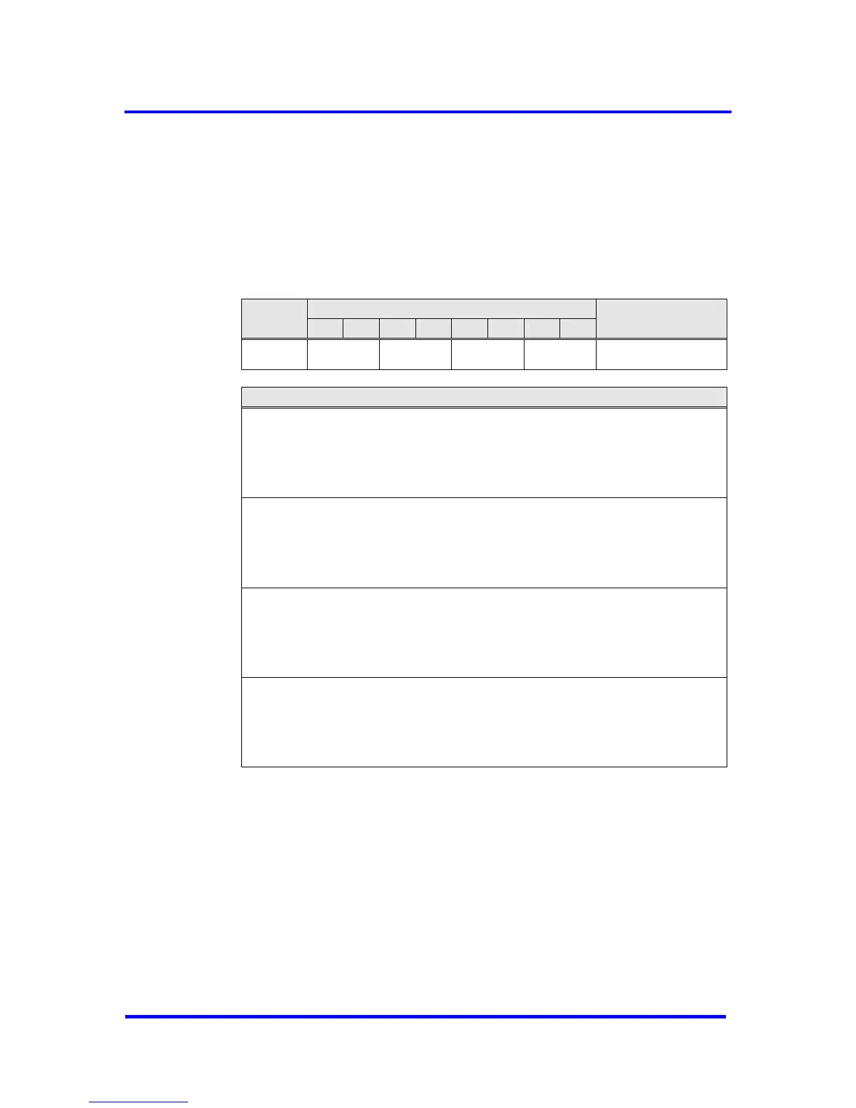
Bit Position
Address
7 6 5 4 3 2 1 0
Designation
0AH F U N D Dout_Buffer_SM
Dout_Buffer_SM, Address 0AH:
bit 7-6
F: Assignment of the F-Buffer
00 = Nil
01 = Dout_Buf_Ptr1
10 = Dout_Buf_Ptr2
11 = Dout_Buf_Ptr3
bit 5-4
U: Assignment of the U-Buffer
00 = Nil
01 = Dout_Buf_Ptr1
10 = Dout_Buf_Ptr2
11 = Dout_Buf_Ptr3
bit 3-2
N: Assignment of the N-Buffer
00 = Nil
01 = Dout_Buf_Ptr1
10 = Dout_Buf_Ptr2
11 = Dout_Buf_Ptr3
bit 1-0
D: Assignment of the D-Buffer
00 = Nil
01 = Dout_Buf_Ptr1
10 = Dout_Buf_Ptr2
11 = Dout_Buf_Ptr3
Figure 6-12: Dout-Buffer Management
When reading the Next_Dout_Buffer_Cmd the user gets the information
which buffer (‘U’ buffer) belongs to the user after the change, or whether a
change has taken place at all.
VPC3+C User Manual
Revision 1.03 47
Copyright © profichip GmbH 2004-2006