6 PROFIBUS DP Interface
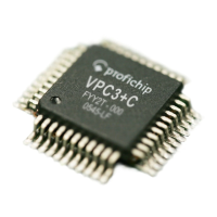
Bit Position
Address
7 6 5 4 3 2 1 0
Designation
0BH 0 0 0 0
U_Buffer_
Cleared
State_U_
Buffer
Ind_U_
Buffer
Next_Dout_
Buf_Cmd
See coding
below
Next_Dout_Buf_Cmd, Address 0BH:
bit 7-4
Don’t care: Read as ‘0’
bit 3
U_Buffer_Cleared: User-Buffer-Cleared Flag
0 = U buffer contains data
1 = U buffer is cleared
bit 2
State_U_Buffer: State of the User-Buffer
0 = no new U buffer
1 = new U buffer
bit 1-0
Ind_U_Buffer: Indicated User-Buffer
01 = Dout_Buf_Ptr1
10 = Dout_Buf_Ptr2
11 = Dout_Buf_Ptr3
Figure 6-13: Coding of Next_Dout_Buf_Cmd
The user must clear the ‘U’ buffer during initialization so that defined
(cleared) data can be sent for a RD_Output telegram before the first data
cycle.
Reading Inputs
The VPC3+C sends the input data from the ‘D’ buffer. Prior to sending, the
VPC3+C fetches the Din-Buffer from ‘N’ to ‘D'. If no new buffer is present in
‘N', there is no change.
The user makes the new data available in ‘U’. With the
New_Din_Buffer_Cmd, the buffer changes from ‘U’ to ‘N’. If the user’s
preparation cycle time is shorter than the bus cycle time, not all new input
data are sent, but just the most current. At a 12 Mbit/s baud rate, it is more
likely, however, that the user’s preparation cycle time is larger than the bus
cycle time. Then the VPC3+C sends the same data several times in
succession.
During start-up, the VPC3+C does not go to DATA-EXCH before all
parameter telegrams and configuration telegrams have been
acknowledged.
48 Revision 1.03
VPC3+C
User Manual
Copyright © profichip GmbH 2004-2006