The fault indicating/pacing relay can be retrofitted and is opera‐
tional once attached to the relay board - refer to the "Retrofitting
relays" supplementary instructions.
Electrical interface
for semiconductor switch pacing relay:
Data Value Unit
Max. residual voltage at I
off max
= 1 µA 0.4 V
Pacing pulse duration, approx. 100 ms
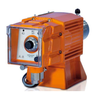
To pin VDE cable Contact Relay
1 yellow N/O (normally open) Relay 1
4 Green C (common) Relay 1
3 white N/O (normally open) Relay 2
2 brown C (common) Relay 2
9.3.5.4 "Current output plus relay" output (identity code C)
A relay combined with a current output can be ordered as an
option. The relay either switches as a fault indicating relay in the
event of a fault on the pump and with "Liquid level low 1st stage"
warning message and "Liquid level low 2nd stage" fault messages
or is used as a pacing relay.
The behaviour is factory-programmed. If another switching function
is wished, the pump can be reprogrammed in the
‘Relay’
menu.
The variable to be signalled for the current output can be selected
in the
‘ANALOGUE OUTPUT’
menu.
The current output plus relay can be retrofitted and operates once
it is plugged into the board.
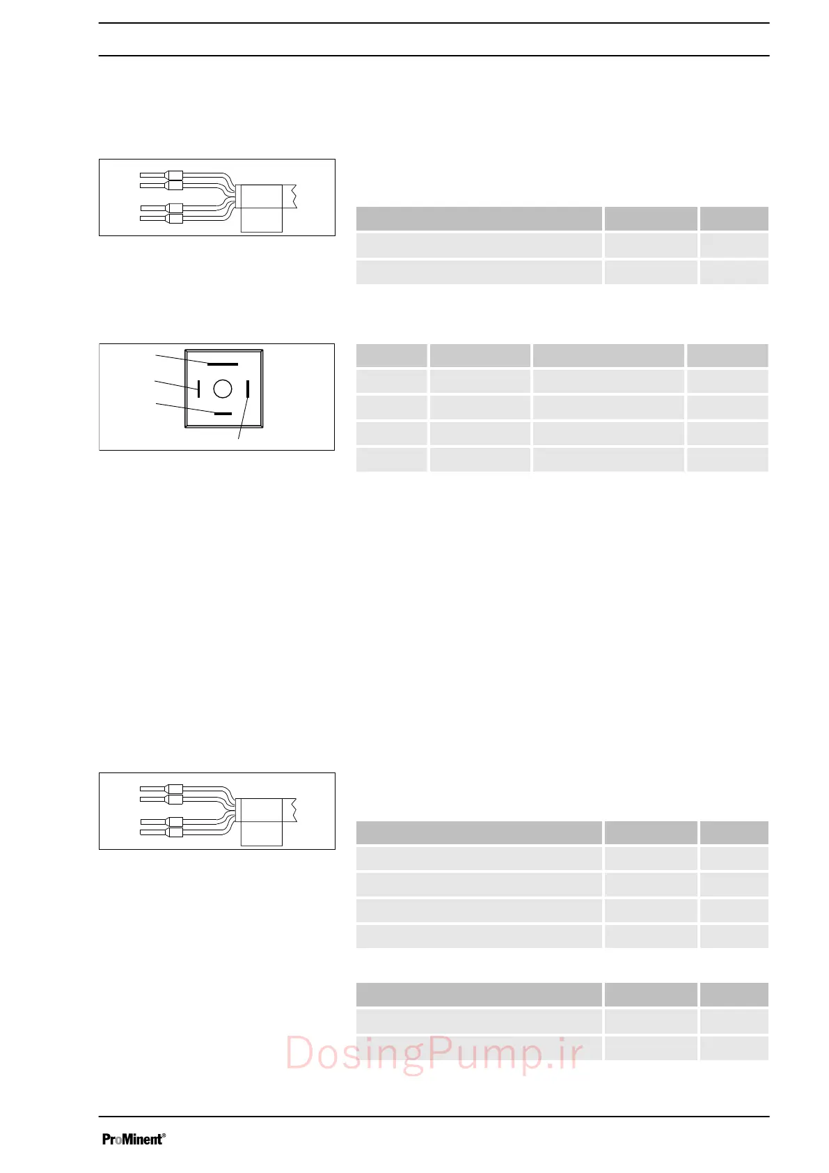
Electrical interface
for current output
Data Value Unit
Open circuit voltage: 8 V
Current range: 4 ... 20 mA
Ripple, max.: 80 μA ss
Load, max.: 250 Ω
for semiconductor switch ("relay"):
Data Value Unit
Max. residual voltage at I
off max
= 1 µA 0.4 V
Pacing pulse duration, approx. 100 ms
Fig. 26: Assignment on the cable
Identity code 4
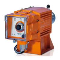
Fig. 27: Assignment on the pump
Fig. 28: Assignment on the cable
Installation, electrical
47
DosingPump.ir

 Loading...