8 Basic tips on setting up and assembling the machine
15 of 54
8.3. Connecting the cabling
Caution!
Connect the mains cable to the CNC control MCS at the very last and make sure the
mains switch at the rear of the CNC control is set to "O", meaning switched off! Do not in
any case switch on any electrical device, be it the computer, the CNC control, or the
machine itself before the connection of the cables is completed!
The connection sockets on the CNC control are all located at the rear of the housing:
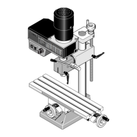
The connection cable of the two stepping motors is inserted in the provided sockets of
the CNC control. They are identified accordingly as "X" and "Z" of the respective CNC
axes. For your information: The X axis is the axis diagonal to the machining direction,
and the Z axis is the axis that is longitudinal to the machining direction.
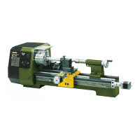
The mains cable of the lathe is inserted in the provided socket at the rear of the CNC
control. The main spindle motor is switched on and off by the CNC programs.
Please leave the insertion of the mains plug of the computer and the CNC control in the
mains socket outlet for the very last.
The communications cable included in the delivery is used to connect the CNC control to
the control computer. It is inserted in the appropriate socket at the control and connected
to a serial interface at the computer.
These are often called "serial" or "COM" and usually have 9 pins. If the connector at
your computer has 25 pins instead of 9, you will need a corresponding adapter.
 Loading...