EasyManuals Logo

Proxxon PD 400 CNC User Manual

Proxxon PD 400 CNC
54 pages
To Next Page IconTo Next Page
To Previous Page IconTo Previous Page
Page #8 background imageLoading...
Page #8 background image
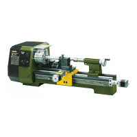
3View of the machine with its elements
8 of 54
3. View of the machine with its elements
1 Main spindle
2 Lathe chuck
3 Multiple tool holder
4 Gearbox
5 Machine base
6 Tailstock
7 Drive for Z axis
8 Spindle for z axis
9 Position switch z axis
10
Drive for X axis
11
Spindle for x axis
12
Position switch x axis
13
Support
14
Cross slide
16
Tool holder element
17
Sleeve
18
Sleeve adjusting wheel
19
Clamping screw for sleeve
20
Clamping screw for tailstock
21
Direction of rotation switch
22
Operational display
23
Multiple-contact switch for speed adjustment
24
Speed table
25
Flange surface for milling unit PF 400 (optional)
26
Travelling lathe centre
26
Ring gear drill chuck
27
Chuck guard
28
Cutting tool
30
Key for chucks
31
Key for lathe chuck
32
Allen key
33
Drill holes for fastening to table

Table of Contents

Questions and Answers:

Question and Answer IconNeed help?

Do you have a question about the Proxxon PD 400 CNC and is the answer not in the manual?

Proxxon PD 400 CNC Specifications

General IconGeneral
BrandProxxon
ModelPD 400 CNC
CategoryTools
LanguageEnglish

Related product manuals