8 Basic tips on setting up and assembling the machine
16 of 54
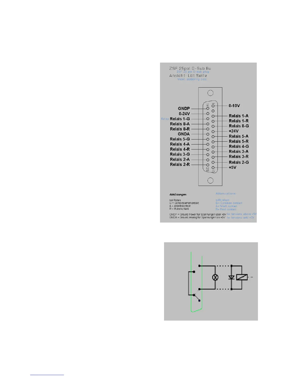
8.4. Additional connection options
Several additional functions can be electronically
driven upon request, such as a coolant pump,
working light, or similar.
The inside of the control has centre-zero relays
whose connections can be executed through the
25-pin socket at the rear of the control. Each
relay has three pins that are identified by the
letters A, R and G. These letters stand for:
A: Make contact
R: Break contact
G: Common contact
The circuit design mode of operation is illustrated
in the picture on the right; both Relays 3 and 4 are
available.

 Loading...