16
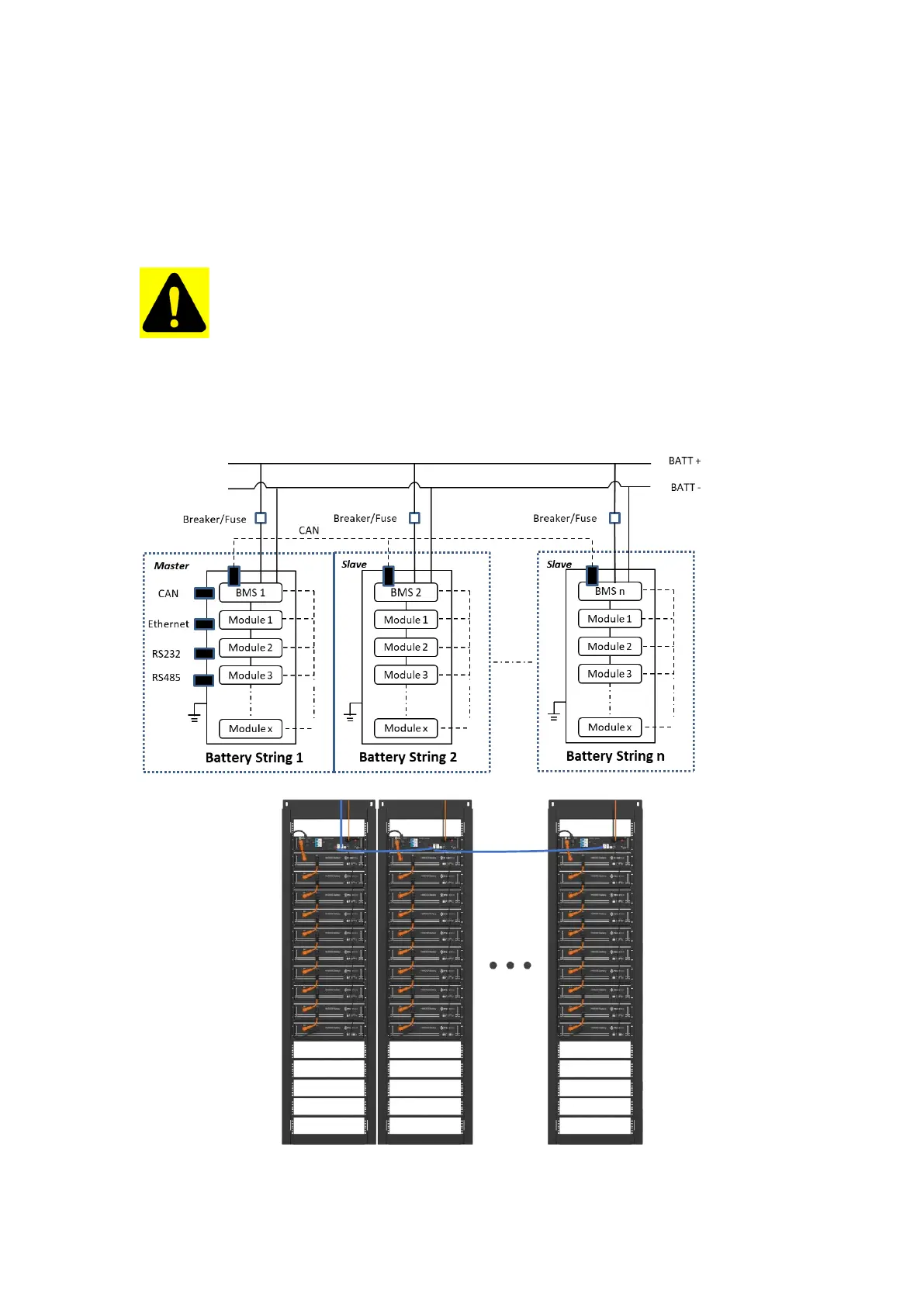
2.6.1. System Diagram without MBMS via CAN
Multiple battery string parallel connection via CAN communication
among BMSs diagram (battery string qty. ≤6 sets). The Battery
Controller with ADD address 1 is the master and all remaining
Battery Controllers are slave. The external interface is only valid
on the Battery Controller with ADD address “1”.
Caution: When an MBMS does not exist, one of the V2 version
control modules can be used as a battery control core to
communicate externally with the PCS and internally to
control the other control modules (V2 version or V1 version).
When both V2 and V1 versions of the control module exist,
the V2 version of the control module must be used as the
master.
2.6.2. Diagram between Control Module and Battery Modules