VOCALISER INSTALLATION MANUAL
Page: 2 RINS119-5
CHAPTER 1: INTRODUCTION
This manual describes how the Vocaliser is connected to a control panel, how to change the
polarities of both inputs and outputs, NVM reset information and other set up functions.
The Vocaliser provides a means of relaying appropriate speech messages to a set of telephone
numbers on specific alarm activations which correspond to the four inputs on the printed circuit
board.
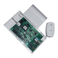
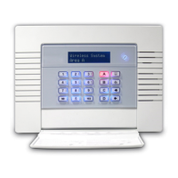
1.1 The Vocaliser PCB
Dimensions: 85 x 145 x 15mm
12 34FLTACK
12V 0V +BAT- SPK M - M+ MIC T T A1 B1 A B
Local
Pro
rammin
Socket
Tamp er
Battery
LED
Relay
(Optional)
NVM
To Telep ho ne
Network
To o ther
telephone
equipment
Inputs
Outputs
Auxillary
Outputs
Battery
Inputs
Speaker/
Microphone
Inputs
Ta mp er
Termi nals
olume
Pot
Status
LEDs
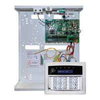
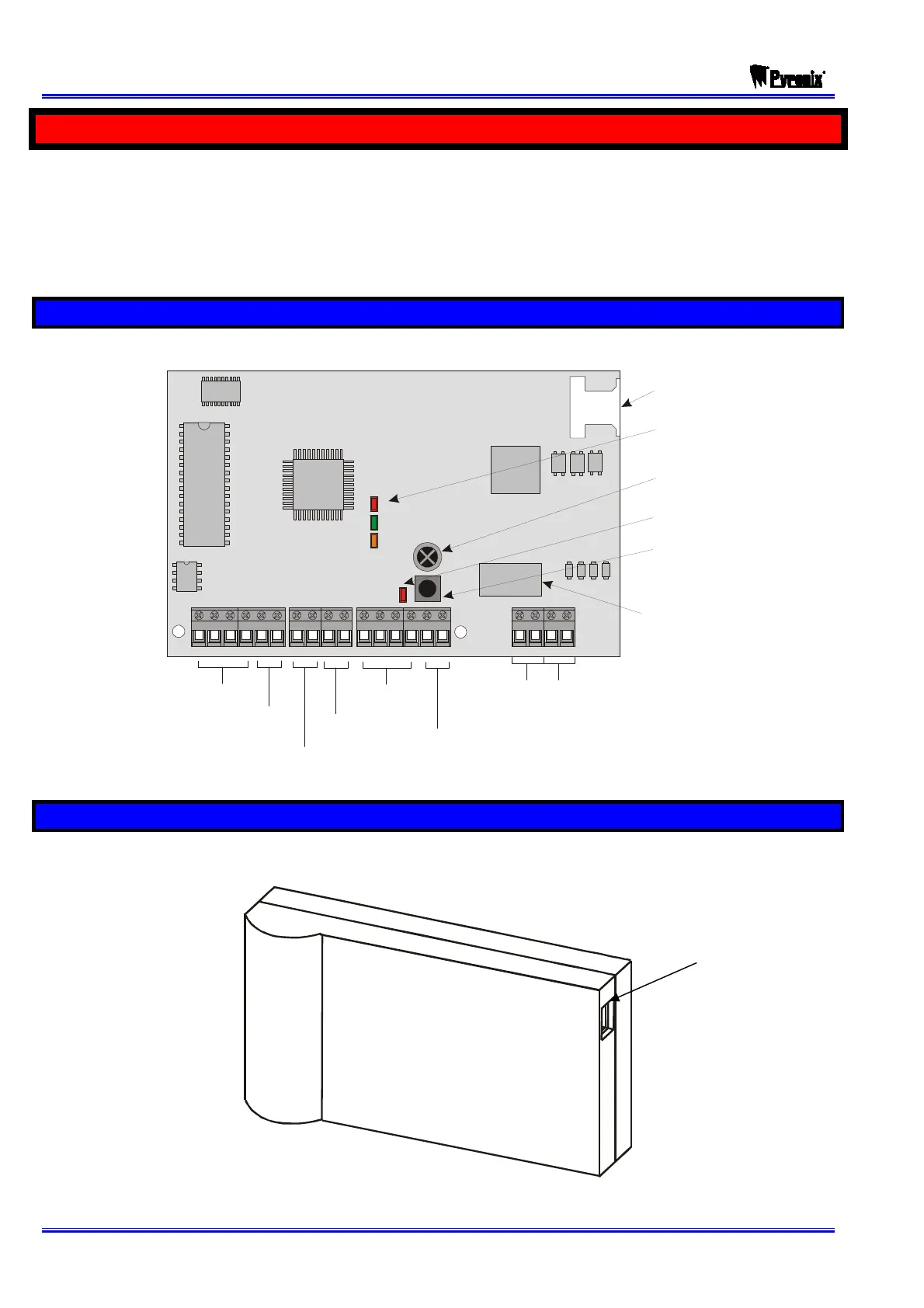
1.2 The Vocaliser Casing
Dimensions: 104 x 185 x 36mm
Local
programming
socket