VOCALISER INSTALLATION MANUAL
RINS119-5 Page: 5
CHAPTER 3: CONNECTIONS / POWERING UP
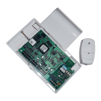
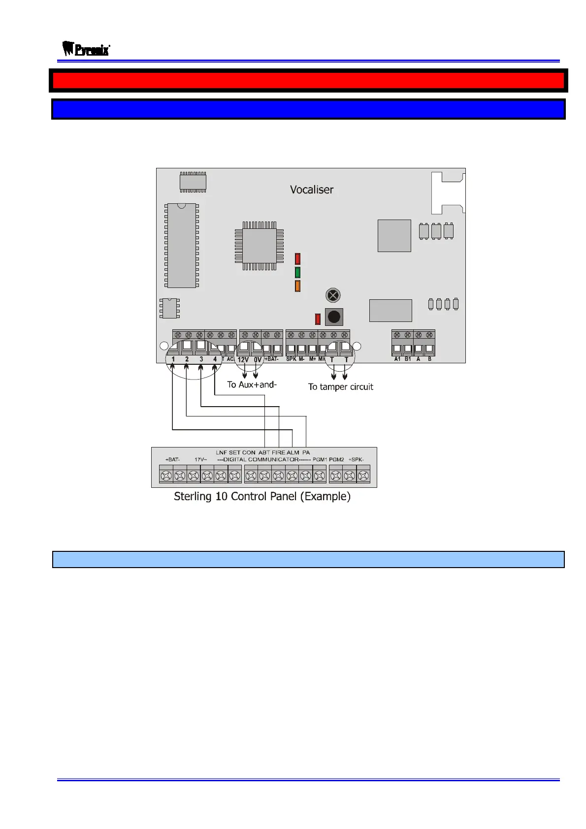
3.1 Connecting the Vocaliser to an Alarm panel
The below example shows the Vocaliser being connected to a Sterling 10 control panel – using
the digital communicator outputs: ALM (alarm), PA (Personal Attack), FIRE, and ABT (Abort).
The default input trigger on the Vocaliser is negative applied, but this may need to be changed
depending on the control panel. Please see page: 12.
3.1.1 Power Supply
The Vocaliser requires a supply of 9-16 volts DC. The installer must make certain that the
alarm system power supply is rated to provide adequate power for this apparatus and for other
auxiliary apparatus drawing power from the alarm system power supply.