ATA Bus Interface and ATA Commands
Quantum Fireball Plus AS 10.2/20.5/30.0/40.0/60.0 GB AT 6-3
DD0 17 Bit 0
DD1 15 Bit 1
DD2 13 Bit 2
DD3 11 Bit 3
DD4 9 Bit 4
DD5 7 Bit 5
DD6 5 Bit 6
DD7 3 Bit 7
DD8 4 Bit 8
DD9 6 Bit 9
DD10 8 Bit 10
DD11 10 Bit 11
DD12 12 Bit 12
DD13 14 Bit 13
DD14 16 Bit 14
DD15 18 Bit 15
Ground Ground — 19 Ground between the host system and the drive.
Keypin KEYPIN — 20 Pin removed to key the interface connector.
DMA Request DMARQ OUT 21 Asserted by the drive when it is ready to exchange
data with the host. The direction of the data
transfer is determined by DIOW– and DIOR–.
DMARQ is used in conjunction with DMACK–. The
drive has a 10kW pull-down resistor on this signal.
Ground Ground — 22 Ground between the host system and the drive.
I/O Write DIOW– IN 23 The rising edge of this write strobe provides a
clock for data transfers from the host data bus
(DD0–DD7 or DD0–DD15) to a register or to the
drive’s data port.
Ground Ground — 24 Ground between the host system and the drive.
I/O Read DIOR– IN 25 The rising edge of this read strobe provides a clock
for data transfers from a register or the drive’s
data port to the host data bus (DD0–DD7 or DD0–
DD15). The rising edge of DIOR– latches data at
the host.
Ground Ground — 26 Ground between the host system and the drive.
I/O Channel Ready IORDY OUT 27 When the drive is not ready to respond to a data
transfer request, the IORDY signal is asserted
active low to extend the host transfer cycle of any
host register read or write access. When IORDY is
deasserted, it is in a high-impedance state and it is
the host’s responsibility to pull this signal up to a
high level (if necessary).
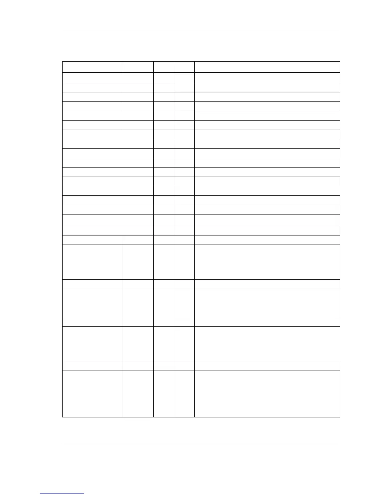
Table 6-1
Table 6-1 Table 6-1
Table 6-1
Drive Connector Pin Assignments (J1, Section C) (Continued)
SIGNAL
SIGNALSIGNAL
SIGNAL NAME
NAMENAME
NAME DIR
DIRDIR
DIR PIN
PINPIN
PIN DESCRIPTION
DESCRIPTIONDESCRIPTION
DESCRIPTION