Installation
3-10 Quantum Fireball Plus AS 10.2/20.5/30.0/40.0/60.0 GB AT
Figure 3-8
Figure 3-8 Figure 3-8
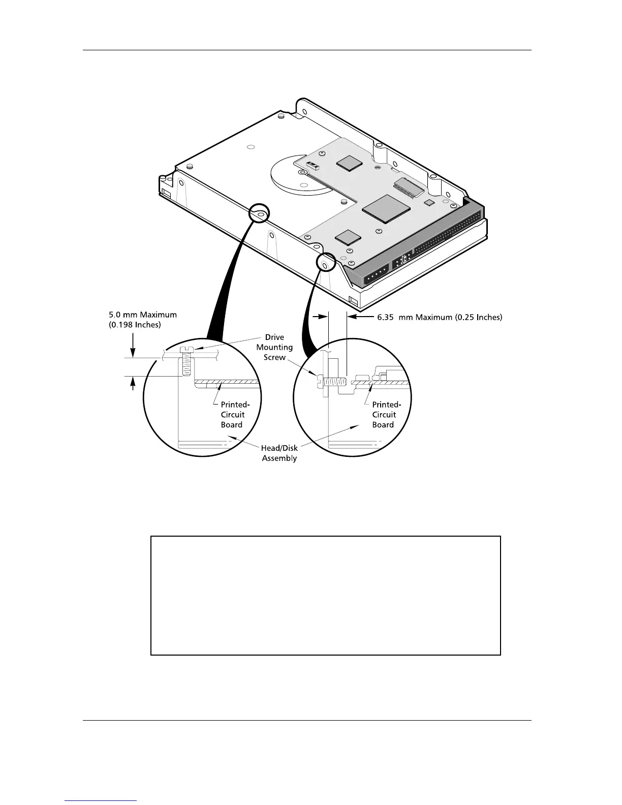
Figure 3-8 Mounting Screw Clearance for the Quantum Fireball Plus AS Hard Disk Drives
CAUTION:
CAUTION:CAUTION:
CAUTION: The PCB is very close to the mounting holes. Do not ex-
ceed the specified length for the mounting screws. The
specified screw length allows full use of the mounting
hole threads, while avoiding damaging or placing un-
wanted stress on the PCB. Figure 3-8 specifies the min-
imum clearance between the PCB and the screws in the
mounting holes. To avoid stripping the mounting hole
threads, the maximum torque applied to the screws must
not exceed 8 inch-pounds. A maximum screw length of
0.25 inches may be used.