ATA Bus Interface and ATA Commands
6-22 Quantum Fireball Plus AS 10.2/20.5/30.0/40.0/60.0 GB AT
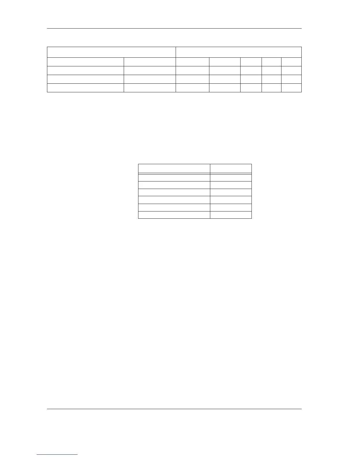
After power on or following a reset, the drive initializes the Command Block
Registers to the values shown in Table 6-11.
Table 6-11
Table 6-11 Table 6-11
Table 6-11
Command Block Register Initial Values
6.6
6.66.6
6.6 REGISTER DESCRIPTIONS
REGISTER DESCRIPTIONSREGISTER DESCRIPTIONS
REGISTER DESCRIPTIONS
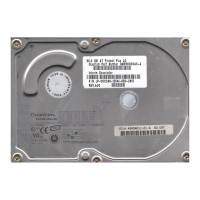
The Quantum Fireball Plus AS 10.2/20.5/30.0/40.0/60.0 GB AT hard disk drives
emulate the ATA Command and Control Block Registers. Functional descriptions
of these registers are given in the next two sections.
6.6.1
6.6.16.6.1
6.6.1 Control Block Registers
Control Block RegistersControl Block Registers
Control Block Registers
6.6.1.1
6.6.1.16.6.1.1
6.6.1.1 Alternate Status Register
Alternate Status RegisterAlternate Status Register
Alternate Status Register
The Alternate Status Register contains the same information as the Status Register
in the command block. Reading the Alternate Status Register does not imply the
acknowledgment of an interrupt by the host or clear a pending interrupt. See the
description of the Status Register in section 6.6.2.8 for definitions of bits in this
register.
Drive/Head
4
Drive/Head A N 1 1 0
LBA Bits 24–27
5
LBA Bits 24–27 A N 1 1 0
Status Command A N 1 1 1
Invalid Address Invalid Address A A X X X
1. N = signal deasserted
2. X = signal either asserted or deasserted
3. A = signal asserted
4. Mapping of registers in CHS mode
5. Mapping of registers in LBA mode
REGISTER
REGISTERREGISTER
REGISTER VALUE
VALUEVALUE
VALUE
Error Register 01
Sector Count Register 01
Sector Number Register 01
Cylinder Low Register 00
Cylinder High Register 00
Drive/Head Register 00
FUNCTION
FUNCTIONFUNCTION
FUNCTION HOST SIGNALS
HOST SIGNALSHOST SIGNALS
HOST SIGNALS