ATA Bus Interface and ATA Commands
Quantum Fireball Plus AS 10.2/20.5/30.0/40.0/60.0 GB AT 6-23
6.6.1.2
6.6.1.26.6.1.2
6.6.1.2 Device Control Register
Device Control RegisterDevice Control Register
Device Control Register
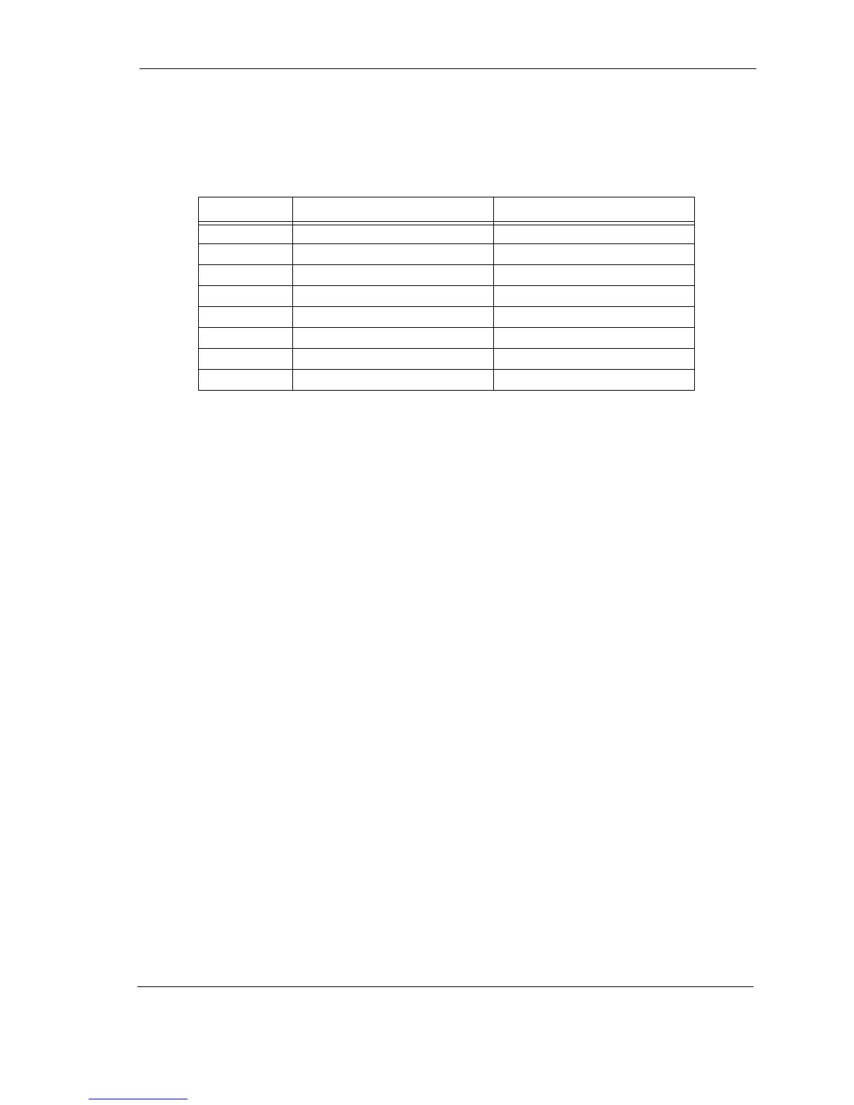
This write-only register contains two control bits, as shown in Table 6-12.
Table 6-12
Table 6-12 Table 6-12
Table 6-12
Device Control Register Bits
BIT
BITBIT
BIT MNEMONIC
MNEMONICMNEMONIC
MNEMONIC DESCRIPTION
DESCRIPTIONDESCRIPTION
DESCRIPTION
7Reserved –
6Reserved –
5Reserved –
4Reserved –
31 Always 1
2SRST
1
1. SRST = Host Software Reset bit. When the host sets this bit, the drive
is reset. When two drives are daisy-chained on the interface, this bit
resets both drives simultaneously.
Host software reset bit
1nIEN
2
2. nIEN = Drive Interrupt Enable bit. When nIEN equals 0 or the host
has selected the drive, the drive enables the host interrupt signal
INTRQ through a tristate buffer to the host. When nIEN equals 1 or
the drive is not selected, the host interrupt signal INTRQ is in a high-
impedance state, regardless of the presence or absence of a pending
interrupt.
Drive interrupt enable bit
00 Always 0