ATA Bus Interface and ATA Commands
Quantum Fireball Plus AS 10.2/20.5/30.0/40.0/60.0 GB AT 6-11
6.4.2.2
6.4.2.26.4.2.2
6.4.2.2 Multiword DMA Transfer Mode
Multiword DMA Transfer ModeMultiword DMA Transfer Mode
Multiword DMA Transfer Mode
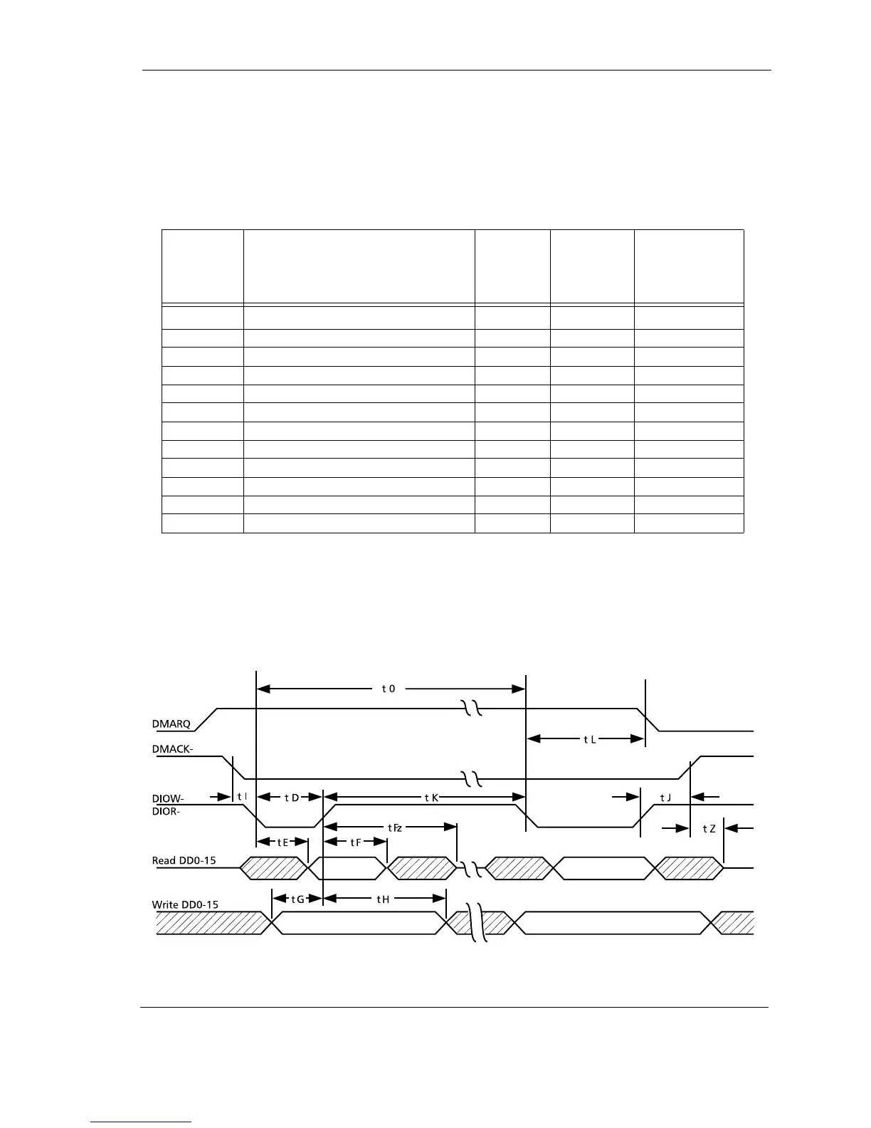
The multiword DMA host interface timing shown in Table 6-6 is in reference to
signals at 0.8 volts and 2.0 volts. All times are in nanoseconds, unless otherwise
noted. Figure 6-2 provides a timing diagram.
Table 6-6
Table 6-6 Table 6-6
Table 6-6
Multiword DMA Host Interface Timing
Figure 6-2
Figure 6-2 Figure 6-2
Figure 6-2 Multiword DMA Bus Interface Timing
SYMBOL
SYMBOLSYMBOL
SYMBOL DESCRIPTION
DESCRIPTIONDESCRIPTION
DESCRIPTION MIN/MAX
MIN/MAXMIN/MAX
MIN/MAX
MODE 2
MODE 2MODE 2
MODE 2
1
11
1
(local bus)
(local bus)(local bus)
(local bus)
1. ATA Mode 2 timing is listed for reference only.
Quantum
Quantum Quantum
Quantum
Fireball Plus
Fireball Plus Fireball Plus
Fireball Plus
AS
ASAS
AS
AT
ATAT
AT
t0
t0t0
t0 Cycle Time
Cycle TimeCycle Time
Cycle Time min
minmin
min
120 120
tD DIOR–/DIOW– Pulsewidth min 70 70
tE DIOR– to Data Valid max – –
tF DIOR– Data Hold min 5 5
tFz DIOR– Data Tristate
2
2. The Quantum Fireball Plus AS 10.2/20.5/30.0/40.0/60.0 GB AT drive tristates
after each word transferred.
max 20 20
tG DIOW– Data Setup min 20 20
tH DIOW– Data Hold min 10 10
tI DMACK to DIOR–/DIOW– Setup min 0 0
tJ DIOR–/DIOW– to DMACK– Hold min 5 5
tK DIOR–/DIOW– Negated Pulsewidth min 25 25
tL DIOR–/DIOW– to DMARQ Delay max 35 35
tz DMACK– Data Tristate
3
3. Symbol tz only applies on the last tristate at the end of a multiword DMA transfer
cycle.
max 25 25