ATA Bus Interface and ATA Commands
6-26 Quantum Fireball Plus AS 10.2/20.5/30.0/40.0/60.0 GB AT
6.6.2.6
6.6.2.66.6.2.6
6.6.2.6 Cylinder High Register
Cylinder High RegisterCylinder High Register
Cylinder High Register
The Cylinder High Register contains the eight high-order bits of the starting
cylinder address for any disk access. On multiple sector transfers that cross cylinder
boundaries, the drive updates this register at the completion of command
execution, to reflect the current cylinder number. The host loads the most
significant bits of the cylinder address into the Cylinder High Register.
In LBA mode, this register contains bits 16 to 23. At command completion, the host
updates this register to reflect the current LBA bits 16 to 23.
6.6.2.7
6.6.2.76.6.2.7
6.6.2.7 Drive/Head Register
Drive/Head RegisterDrive/Head Register
Drive/Head Register
The Drive/Head Register contains the drive ID number and its head numbers. At
command completion this register is updated by the drive to reflect the current
head.
In LBA mode, this register contains bits 24 to 27. At command completion, the
drive updates this register to reflect the current LBA bits 24 to 27.
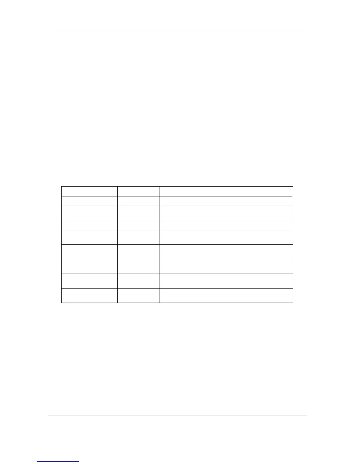
Table 6-15 shows the Drive/Head Register bits.
Table 6-15
Table 6-15 Table 6-15
Table 6-15
Drive Head Register Bits
MNEMONIC
MNEMONICMNEMONIC
MNEMONIC BIT
BITBIT
BIT DESCRIPTION
DESCRIPTIONDESCRIPTION
DESCRIPTION
Reserved 7
1
1. Bits 5–7 define the sector size set in hardware (512 bytes).
Always
1
L6
2
2. Bit 6 is the binary encoded Address Mode Select. When bit 6 is set to 0,
addressing is by CHS mode. When bit 6 is set to 1, addressing is by LBA mode.
0
for CHS mode
1
for LBA mode
Reserved 5 Always
1
DRV 4
3
3. Bit 4 (DRV) contains the binary encoded drive select number. The Master is
the primary drive; the Slave is the secondary drive
0
indicates the Master drive is selected
1
indicates the Slave drive is selected
HS3 3
4
4. In CHS mode, bits 3–0 (HS0–HS3) contain the binary encoded address of the
selected head. At command completion, the host updates these bits to reflect
the address of the head currently selected. In LBA mode, bits 3–0 (HS0–HS3)
contain bits 24–27 of the LBA Address. At command completion, the host
updates this register to reflect the current LBA bits 24 to 27.
Most significant Head Address bit in CHS mode
Bit 24 of the LBA Address in LBA mode
HS2 2 Head Address bit for CHS mode
Bit 25 of the LBA Address in LBA mode
HS1 1 Head Address bit for CHS mode
Bit 26 of the LBA Address in LBA mode
HS0 0 Least significant Head Address bit in CHS mode
Bit 27 of the LBA Address in LBA mode