Wi-Fi&Bluetooth Module Series
FC64E_Hardware_Design
27
/ 53
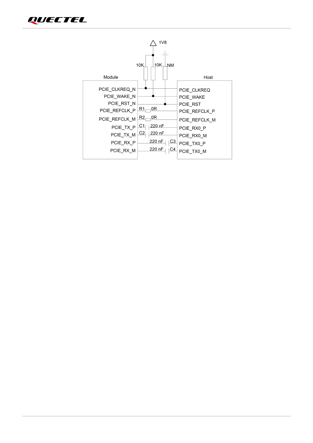
Figure 6: PCIe Interface Connection
To ensure the signal integrity of PCIe interface, C1 and C2 should be placed close to the module, and C3
and C4 should be placed close to the host. The extra stubs of traces must be avoided.
The following principles of PCIe interface design should be complied with, so as to meet PCIe Gen3
specifications.
It is important to route PCIE_TX_P/M, PCIE_RX_P/M, and PCIE_REFCLK_P/M as differential pairs
with total grounding. And the differential impedance should be 85 Ω ±10 %.
The maximum trace length of each differential pair (PCIE_TX_P/M, PCIE_RX_P/M, and
PCIE_REFCLK_P/M) should be less than 200 mm, and trace length matching within each differential
pair should be less than 0.5 mm.
Space between PCIe signals and all other signals (inter-interface) should be four times the trace
width.
Do not route signal traces under crystals, oscillators, magnetic devices, or RF signal traces. It is
important to route the PCIe differential traces in inner-layer of the PCB and surround the traces with
ground on that layer and with ground planes above and below.
3.6. Bluetooth Application Interface
The following figure shows the block diagram of Bluetooth application interface connection between the
module and the host.