5.4 Marker Inputs
In addition to the channel inputs, the device features marker inputs that insert marker
timestamps in the timeline. They can be connected e.g., to some pixel clock or line clock in order
to help sorting the timestamps. The GPIO Connector is used for those inputs:
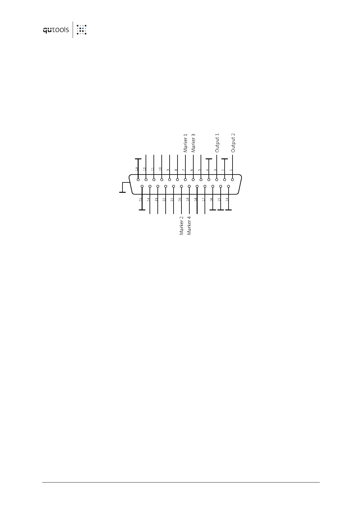
Figure 4: D-Sub connector at the back panel
Marker inputs 1...4 reside on pins 7, 6, 20, 19. Use the additionally shipped breakout cable.
If configured by software, Marker events are saved within the data stream as timestamps.
Channel numbers 100-103 are the Markers 1-4 with rising edge and 105-108 with falling edge.