5.5 Output Channels
In addition to the channel inputs, the device features 2 output channels. The two programmable
outputs enable conditional measurements, state preparation, gating of detectors, control of
shutters and more to synchronize events. An adjustable delay can be added on the output signal
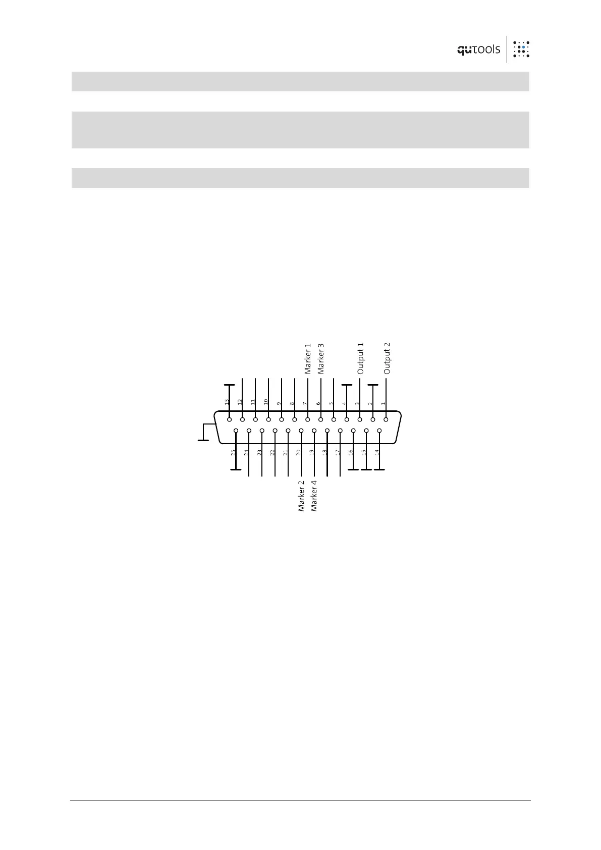
by software. The GPIO Connector is used for those outputs:
Figure 5: D-Sub connector at the back panel
The output channels 1 and 2 reside on pins 3 and 1. Use the additionally shipped breakout cable.