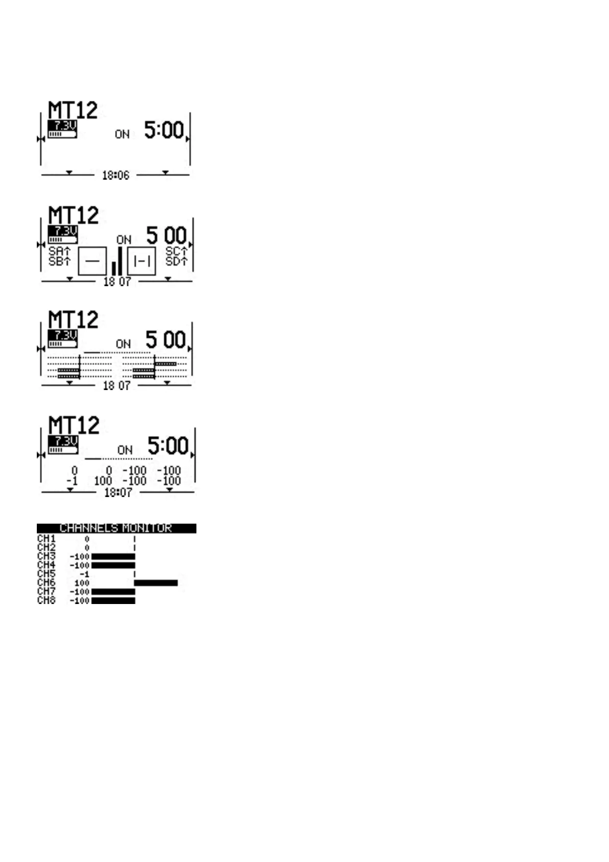
2.2. Main View
Screen 1 - This view displays the model name, trim positions (if trims are
enabled), clock, transmitter battery voltage, Drive mode, receiver signal
strength, and Timers 1 and 2 (if enabled).
Screen 2 - This view displays the model name, trim positions (if trims are
enabled), clock, transmitter battery voltage, Drive mode, receiver signal
strength, and Timer 1 (if enabled). It also has a graphical representation
of the stick, pot, and switch positions.
Screen 3 - This view displays the model name, trim positions (if trims are
enabled), clock, transmitter battery voltage, Drive mode, receiver signal
strength, and Timer 1 (if enabled). It also shows the numerical values of
the output channels, 8 channels per page. Use the [Roller] to scroll thru
the additional pages.
Screen 4 - This view displays the model name, trim positions (if trims are
enabled), clock, transmitter battery voltage, Drive mode, receiver signal
strength, and Timer 1 (if enabled). It also shows the values of output
channels as a bar graph, 8 channels per page. Use the [Roller] to scroll
thru the additional pages.
Screen 5 - This view shows either the channel monitor or mixer monitor,
8 channels per page. Use the roller or dial to scroll thru the additional
pages. Push the [Roller] button to switch between the channel monitor
and mixer monitor.
Long pressing the [Roller] button from the main view screen will show a
pop-up menu with the options below:
• View Notes - Displays the congured model checklist. This opon is only visible if a valid model checklist le
is in the Models folder.
• Reset - See Reset page.
• Stascs - See Stascs page.
• About - Displays the EdgeTX rmware version being used by the radio.