• Posions - The type of buon that will be simulated.
o Push - will only map to one buon
o 2POS - 8 POS - will map to the number of buons that the switch has (ex: 3POS will map to 3
buons).
• Buon No: The buon number that the output will be mapped to and sent to the target device as.
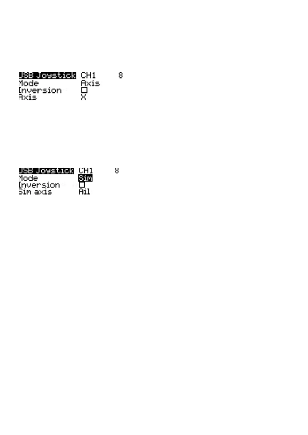
Axis mode opons for a selected channel
Axis - The channel is used to simulate an axis and will be mapped to one of the target device's default axes.
• Axis opons are: X, Y, Z, rotX (rotaon x), rotY, rotZ
Sim mode opons for selected channel
Sim - The channel is used to simulate a common sim axis and it will be listed on the target device as the selected
opon (ex: Thr)
• Sim Axis opons are: Ail, Ele, Rud, Thr
3.2. Drive Modes
Drive modes allow you to have dierent trim sengs for each Drive mode. Once mulple Drive modes are
congured, you can adjust the trim sengs in each Drive mode without aecng the trim sengs in other Drive
modes (unless they are congured to do so). There are nine possible Drive modes, with Drive mode 0 being the
default mode.
 Loading...