ASSEMBLY
OM 0495SB-A [13]
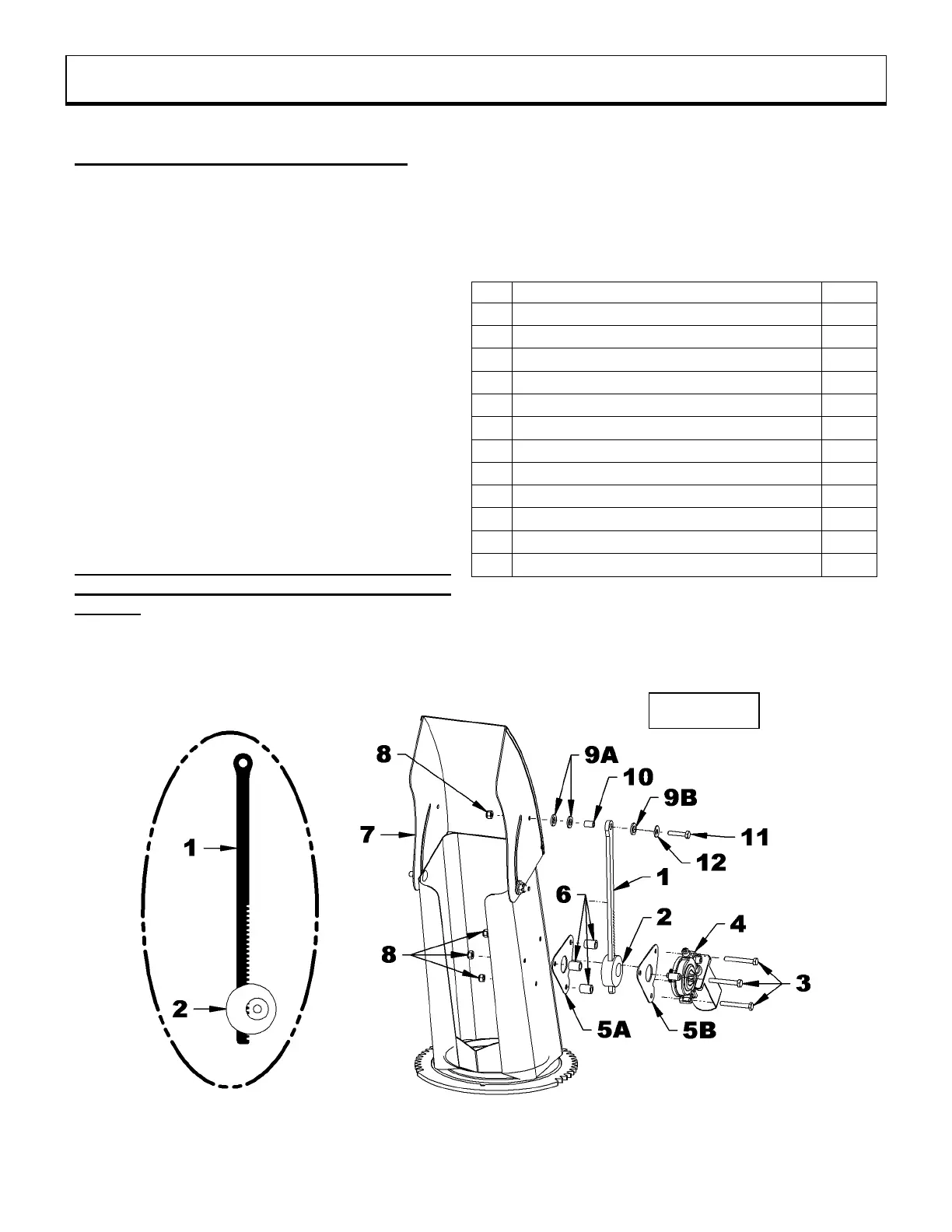
Installation of the electric deflector (Figure 1)
1. Figure 1: Apply a light layer of recommended
grease to the teeth of the rack (item 1) and
insert the rack inside the rack guide (item 2) as
shown in the image on the left.
2. Figure 1: Fix the guide plate (item 5A), the
rack guide (item 2), the three spacers (item 6),
the second guide plate (item 5B) and the
electric motor (item 4) ) on the side of the chute
(item 7) using the three 1/4"NC x 2" hex bolts
(item 3) and the nylon insert locknuts (item 8).
3. Figure 1: Apply a light layer of recommended
grease inside the hole in the rack (item 1) insert
the ø3/8" x 19/32" pivot bearing (item 10) and
place two flat nylon washers (item 9A) between
the deflector and the rack, in order to leave a
slight play. Install the remaining nylon washers
(item 9B) on the other side of the rack.
IMPORTANT: The movements of the rack must
not be hampered by the nylon washers
(item 9).
4. Figure 1: Secure using the 1/4"NC x 1 1/4" hex
bolt (item 11), 1/4" flat washer (item 12), nylon
washers (item 9B), ø3/8" x 19/32" pivot pad
(item 10), nylon washers (item 9A) and 1/4"
nylon insert locknut (item 8) in the order shown.