ASSEMBLY
OM 0495SB-A [24]
Installing the Rotation Sensor Harness
NOTE: The rotation sensor and the electrical extension harness are not included with this
product.
1. Gather all the items listed in the table in figure
10.
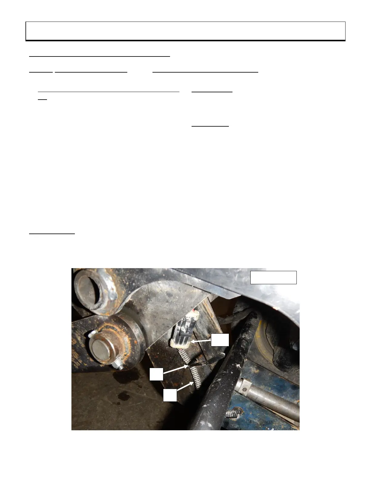
2. Figure 10: Secure the rotation sensor harness
(not included) (item 1) at the location of the
subframe shown in the figure using a 4.8mm x 8"
long nylon tie wrap (item 2).
3. Figure 10a: Assemble the components of the
protective cap, supplied with the snowblower,
according to the figure.
4. Figure 10b: Secure the assembled protective
cap (item 3) to the support reinforcement (item 4)
using a 4.8mm x 8" long nylon tie wrap (item 2).
5. Figure 10b: Attach without tightening the
electric extension harness (not included) (item 5)
to the support reinforcement (item 4) using a
4.8mm x 8" lg nylon tie wrap (item 2a).
IMPORTANT: The extension harness (item 5)
must be able to move in the nylon tie (item 2a).
Figures 10c: The connector of the extension
harness (item 5a) must be attached to the
protective cap (item 3) only when the subframe
is removed from the tractor.
Figure 10d: The extension harness connector
(item 5a) must be attached to the rotation
sensor harness connector (item 1a) only when
the subframe is installed on the tractor.
6. Figure 10b: Secure the extension electrical
harness (item 5) to the metal tube using a
4.8mm x 8" lg nylon tie (item 2).
7. Figure 10e: Secure the extension electrical
harness (item 5) at the location shown in the
figure using a 4.8mm x 8" lg nylon tie wrap
(item 2).
8. Figure 10e: Attach the extension harness
connector (item 5b) to the tractor connector
(item 6).