8. Figure 9f: Pass the harness (item 11)
outside the rubber sheath (item 12) of the
tractor hydraulic control lever.
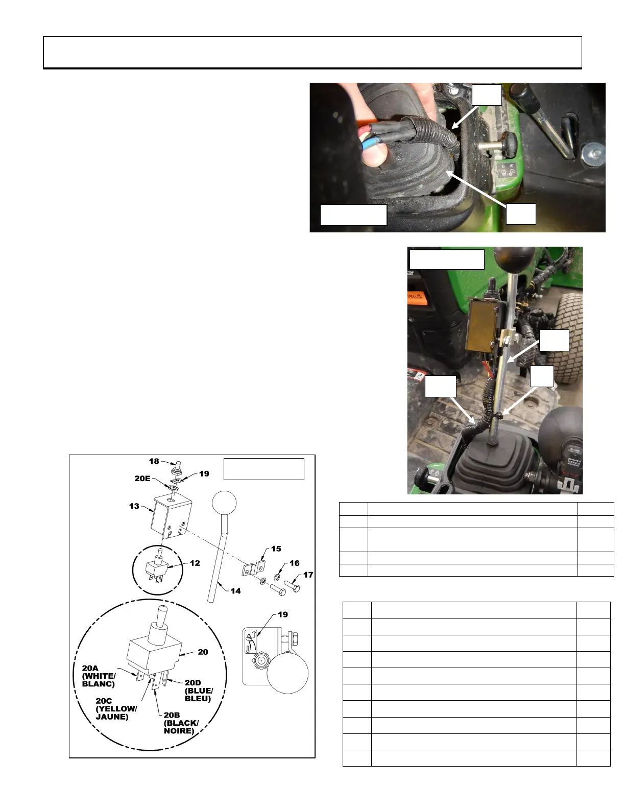
9. Figures 9g, 9h: Attach the connectors of the
main electrical harness (item 11) to the
switch connector (item 20). Attach the white
wire connector to the switch 20A connector,
the black wire to the 20B connector, the
yellow wire to the 20C connector, and the
blue wire to the 20D connector.
10. Figure 9h: Remove the nut (item 20E) from
the switch (item 12) and secure the switch
(item 12) to the switch box (item 13) using the
nut on the switch box (item 20E).
11. Figure 9h: Attach the rubber cap for switch (item 18) to the
switch (item 12).
12. Figure 9h: Secure the switch box (item 13) to the tractor
hydraulic valve lever (item 14) using the housing cramp (item
15) and the two ø1/4" lock washers. (item 16) and two hex bolts
ø1/4"NC x 1" lg. (item 17).
13. Figure 9h: Stick the chute deflector decal (item 19) in the
location shown in the figure.
14. Figure 9g: Attach the main electrical harness (item 11) to the
hydraulic control valve lever (item 14) using a 4.8mm x 8" lg
nylon tie wrap (item 8).