ASSEMBLY
OM 0495SB-A [15]
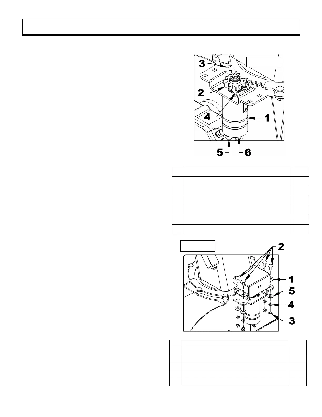
4. Figure 4: If the motor gear (item 2) is not fully
engaged in the teeth of the chute (item 3),
loosen the two right bolts (item 4). Turn the
hydraulic motor (item 1) so that the teeth of
the gear (item 2) connect as much as
possible with the teeth of the chute gear
(item 3). Tighten the bolts (item 4) to a torque
of 10 lb-ft (13 N-M). Do not use the Torque
Table at the end of the manual for these
bolts.
5. Figure 4: Install a green identification ring on
the hydraulic hose (item 5), and install a
yellow identification ring on the hydraulic
hose (item 6). Position the identification rings
as close as possible to the quick couplings.
NOTE: The two other identification rings will
be installed while connecting the snowblower
to the subframe.
6. Figure 4a: Place the gear protector (item 1)
on the frame and secure with the four
5/16"NC x 3/4" bolts, flat washers,
lockwashers and nuts (items 2, 3, 4 , 5)