ESP-SMT Smart Modular Control System
68
F
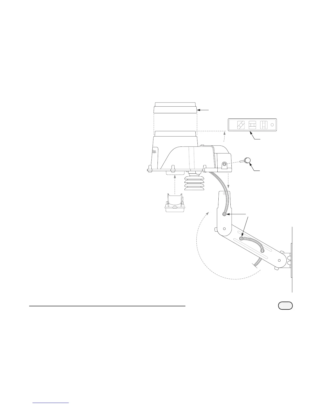
Feed the wire(s) through the three holes
located in the mounting arms to provide a
“strain relief’.
G
Unscrew the captured screw of the wiring
compartment cover to expose the sensor
housing and green wire connector within the
wiring compartment.
H
Strip the two communication wire leads 1/4”
and insert into the connectors (polarity is not
important). If the wires are attached to the
ESP-SMT controller and AC power is available,
a green LED will blink. Once communication
has been established between the sensor and
the controller, the LED will illuminate.
I
Re-attach the wiring compartment cover and
route the wire through the two openings.
Then tighten the captured screw to secure the
cover to the housing.
J
Attach the sensor housing assembly to the
top of the mounting arm. Align the mounting
hole on the bracket and the arm and using
the provided thumb screw, attach the sensor
to the mounting bracket assembly.
K
Adjust each of the mounting arms to assure
that the top of the sensor is secured in a level
conguration.
L
Slip the sensor debris cover onto the top of
the sensor.
TIPPING
BUCKET