ESP-SMTe Controller
4
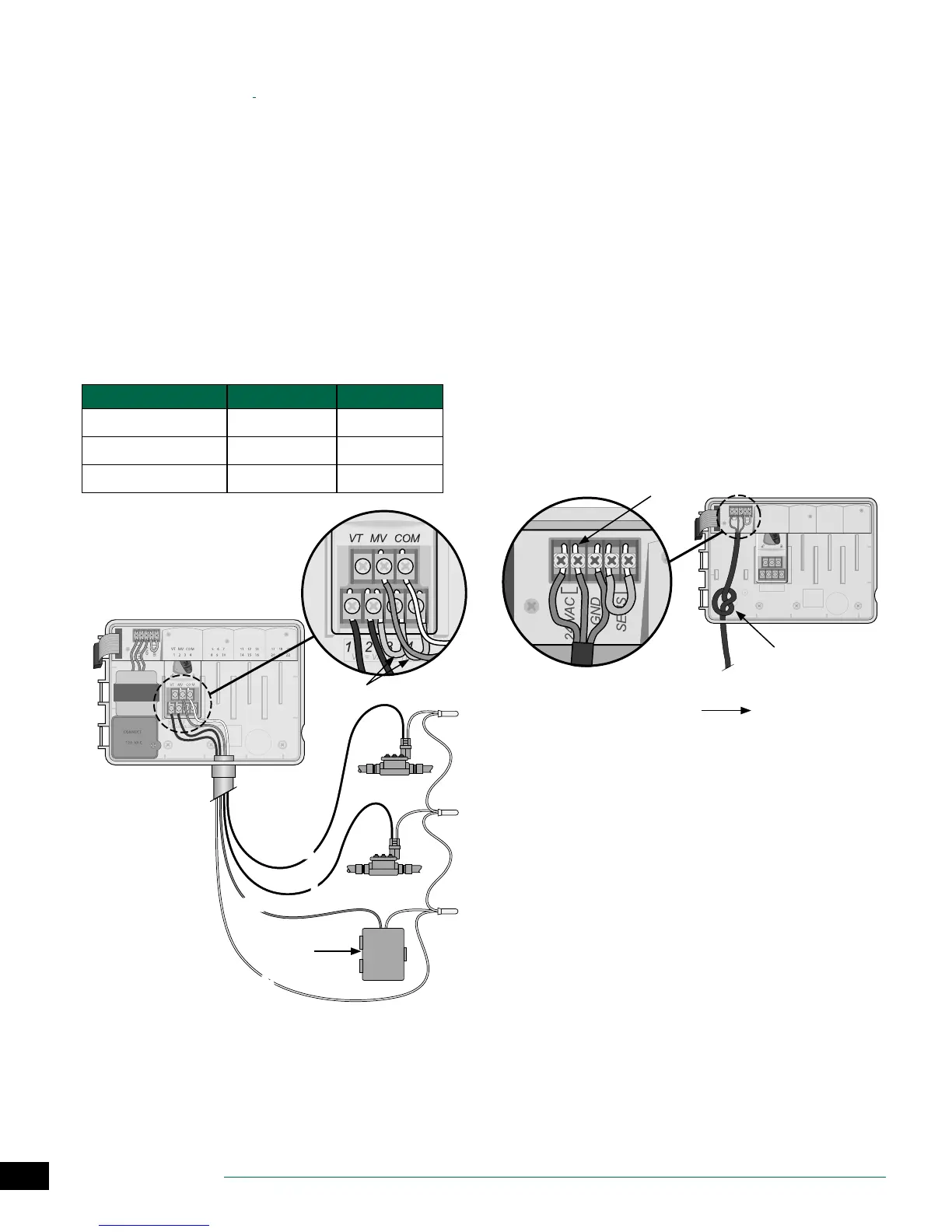
Connect Pump Start Relay (optional)
The ESP-SMTe can control a pump start relay, to turn the
pump on and o as needed.
A
Connect a wire from the pump start relay (PSR) to the
master valve terminal (M) on the base module. Then
connect another wire from the pump start relay to the
eld common wire, as shown.
B
To avoid the possibility of damage to the pump,
connect a short jumper wire from any unused
terminal(s) to the nearest terminal in use, as shown.
NOTE: The ESP-SMTe controller DOES NOT provide
power for a pump. The relay must be wired according
to manufacturer instructions.
Only the following Rain Bird pump start relay models are
compatible with the ESP-SMTe:
Description Note Model No.
Universal Pump Relay 110 volt only PSR110IC
Universal Pump Relay 220 volt only PSR220IC
Dual Pole Pump Relay 110/120 volt PSR110220
NOTE: Connec-
tion to pump
and external
power not
shown. Refer to
pump instal-
lation instruc-
tions.
A
PUMP START
RELAY
B
C
PSR
1
2
Connect Power
WARNING: DO NOT plug in the transformer or con-
nect external power until you have completed and
checked all wiring connections.
WARNING: Electric shock can cause severe injury or
death. Make sure power supply is turned OFF before
connecting power wires.
Indoor Model
A
Route the transformer power cord through the
conduit opening at the bottom left of the unit. Knot
the cable/cord inside the controller cabinet to prevent
it from being pulled out.
WARNING: Do not route the power cord through the
eld wire opening at the bottom right of the unit.
B
Connect the two power wires on the cord to the two
24VAC terminal connections on the controller.
C
Connect the ground wire on the cord to the GND
terminal.
D
Plug the transformer into an electrical outlet.
1234
VT =VALVE T EST
VT MV COM
24 VAC
GND
SENS
VT MV COM 567 11 12 13 17 18 19
1234 8910141516202122
TO EXTERNAL
POWER SUPPLY
D
A
B