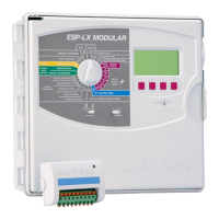
ESP-SMTe Controller
5
Outdoor Model
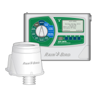
Power Wiring Connections
Black supply wire (hot) to the black transformer wire
White supply wire (neutral) to the white transformer wire
Green supply wire (ground) to the green transformer wire
A
Locate the transformer wiring compartment in
the lower left corner of the controller unit. Use a
screwdriver to remove the cover and expose the
transformer connection wires.
B
Route the three external power source wires through
the conduit opening at the bottom of the unit and
into the wiring compartment.
C
Using the provided wire nuts, connect the external
power source wires (two power and one ground) to
the transformer connection wires inside the wiring
compartment.
WARNING: Ground wire must be connected to
provide electrical surge protection. Permanently
mounted conduit shall be used for connecting main
voltage to the controller.
D
Verify that all wiring connections are secure, then
replace the wiring compartment cover and secure it
with the screw.
1234
VT =VALVE T EST
VT MV COM
24 VAC
GND
SENS
VT MV COM 567 11 12 13 17 18 19
1234 8910141516202122
A
C
B
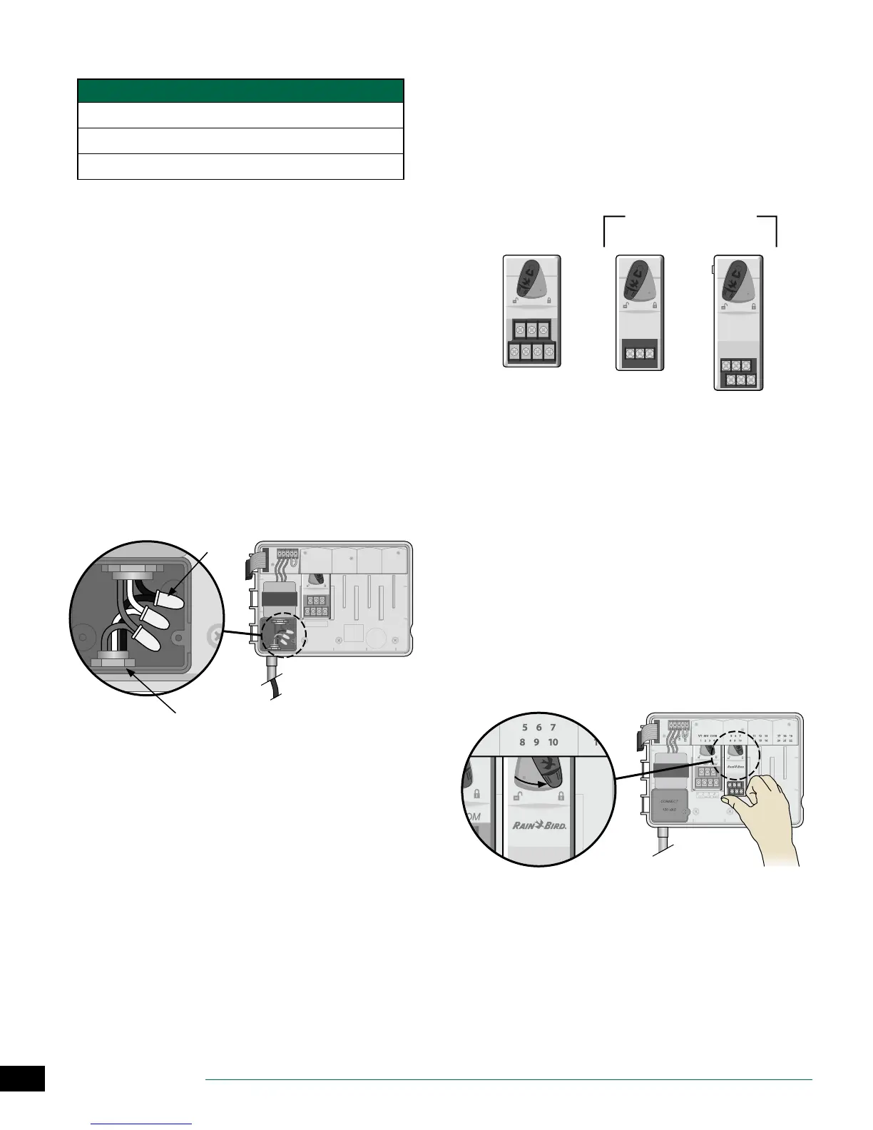
Station Expansion Modules
Optional Station Modules are installed in the empty slots to
the right of the base module to increase the station capac-
ity up to 22 stations.
NOTE: For ideal station sequencing, it is recom-
mended that a 6-Station module always be installed
in Bay 2. For more details see the Station Numbering
section.
VT MV COM
3-STATION
(ESPSM3)
6-STATION
(ESPSM6)
Expansion Modules
(sold separately)
Base Module
(included)
Install Modules
A
Verify the securing lever on the module is in the
unlocked position (slide to the left).
B
Place the module under the desired slot between the
plastic rails.
C
Push the module up into the slot until secure.
D
Slide the securing lever to the locked position (slide
to the right).
REPEAT for additional modules.
NOTE: Modules can be installed or removed with OR
without AC power connected. They are considered
“hot-swappable”.
BC
D