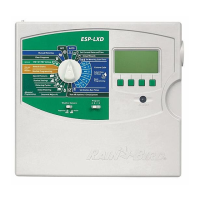
Decoder Controller
NOTE:
!
For additional information about
decoders, please refer to Rain Bird Decoder
System Manual�
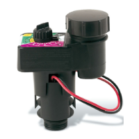
Decoder Design
There are design specifications limiting the length of
the wire path between the controller and decoders
and the decoders and solenoids/valves� The distance
between the decoder and the controller is the Primary
Path and the maximum length depends on the layout�
The distance between the decoder and the solenoid/
valve is the Secondary Path and the maximum length
depends on the wire size� Following are two options
for the wire path layout as well as a breakdown of the
wire path lengths for various wire sizes�
Primary Path
There are two types of layouts for the wire path
between the controller and the decoders, the Star
configuration and the Loop configuration� The Star
configuration is a design where the wire path is
branched throughout the course but where it is not
looped back to the controller�
The Loop configuration is a design where the wire
path is looped back to the controller at the farthest
reach of the layout� The Star configuration is the
recommended layout for the wire path for its ease of
troubleshooting� Only use the Loop configurations
when the wire path length of the Star configuration is
not sufficient to meet your needs�
NOTE:
!
If a Loop configuration is necessary,
install a valve box near the center of the Loop
configuration for ease of troubleshooting�
In a Star configuration, the primary path is the distance
between the controller and the farthest decoder�
In a Loop configuration, the length is measured by
following the wire path around the loop out to the
farthest decoder and back to the controller� The
maximum allowable primary path lengths depend on
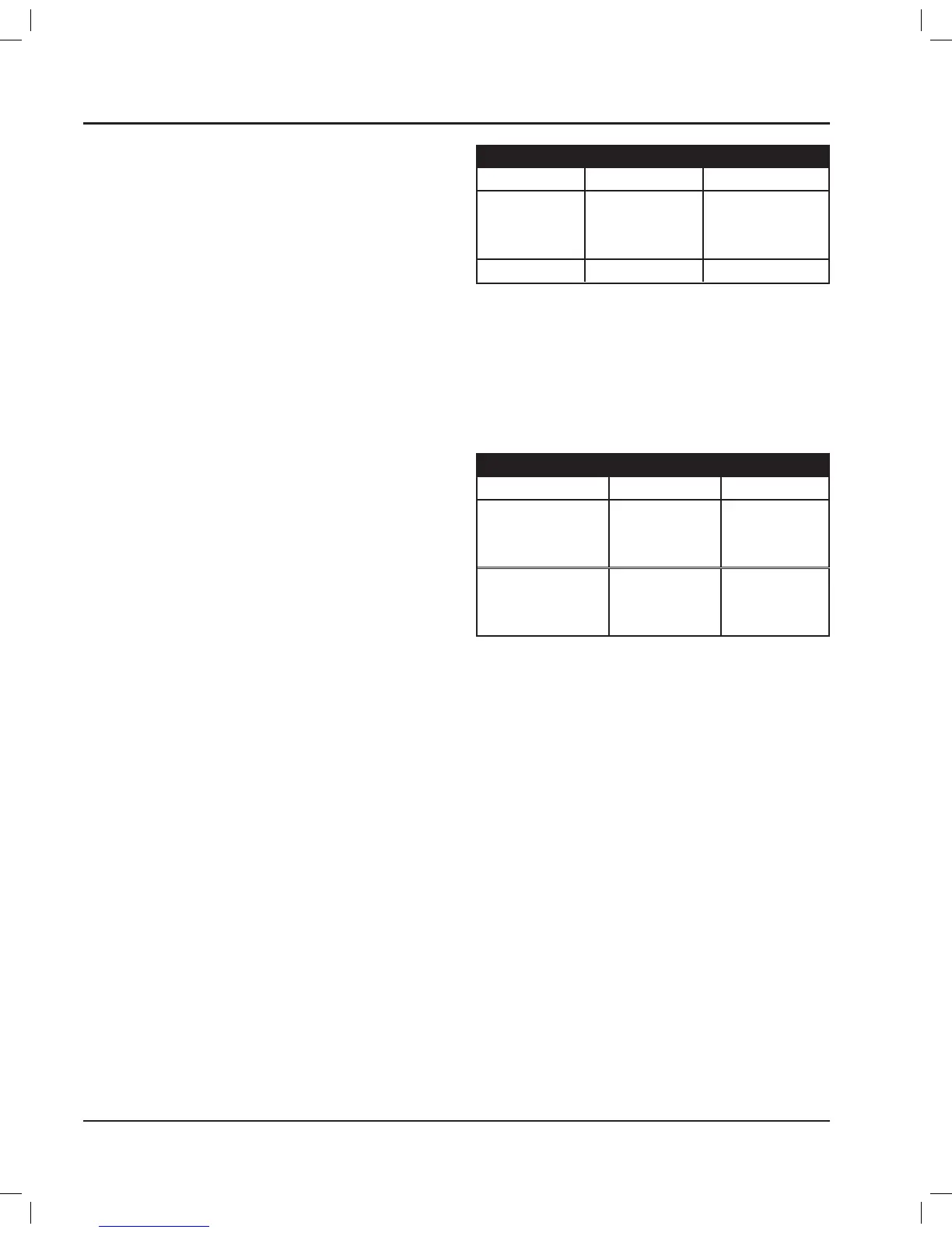
the layout as well as the size of wires� Table 1 lists the
maximum allowable primary path lengths for several
wire sizes�
Maximum Primary Path
Wire Size Star · Miles/km Loop · Miles/km
14 AWG 2�4 / 3�8 9�6 / 15�2
12 AWG 3�8 / 6�1 15�2 / 24�4
10 AWG 6�1 / 9�8 24�4 / 39�2
2�5 mm
2
1�8 / 3�0 7�5 / 12�0
Table 1
Secondary Path
The secondary path is the distance between the
decoder output and the solenoid on the valve-in-
head sprinkler(s) or the remote control valve� The
maximum lengths for the secondary path for several
wire sizes are shown in Table 2�
Maximum Secondary Path
Wire Size Feet Meters
16 AWG 289 88
14 AWG 456 139
12 AWG 720 220
1�5 mm
2
328 100
2�0 mm
2
436 133
2�5 mm
2
545 166
Table 2
NOTE:
!
If two solenoids are connected to
one decoder, the total length is the distance
from the decoder to the first solenoid plus
the distance again from the decoder to the
second solenoid�
Decoder Address
All the decoders connected to one controller must
have a unique four or five digit address code� The
controller uses the address codes to activate each
decoder individually� Setup instructions for the
decoder addresses are included in the PAR+ES
Operation Manual�
PAR+ES Installation Manual12
 Loading...