Install MAXI 2-Wire Interface Board
NOTE:
!
Follow this procedure only for 2-wire
installations�
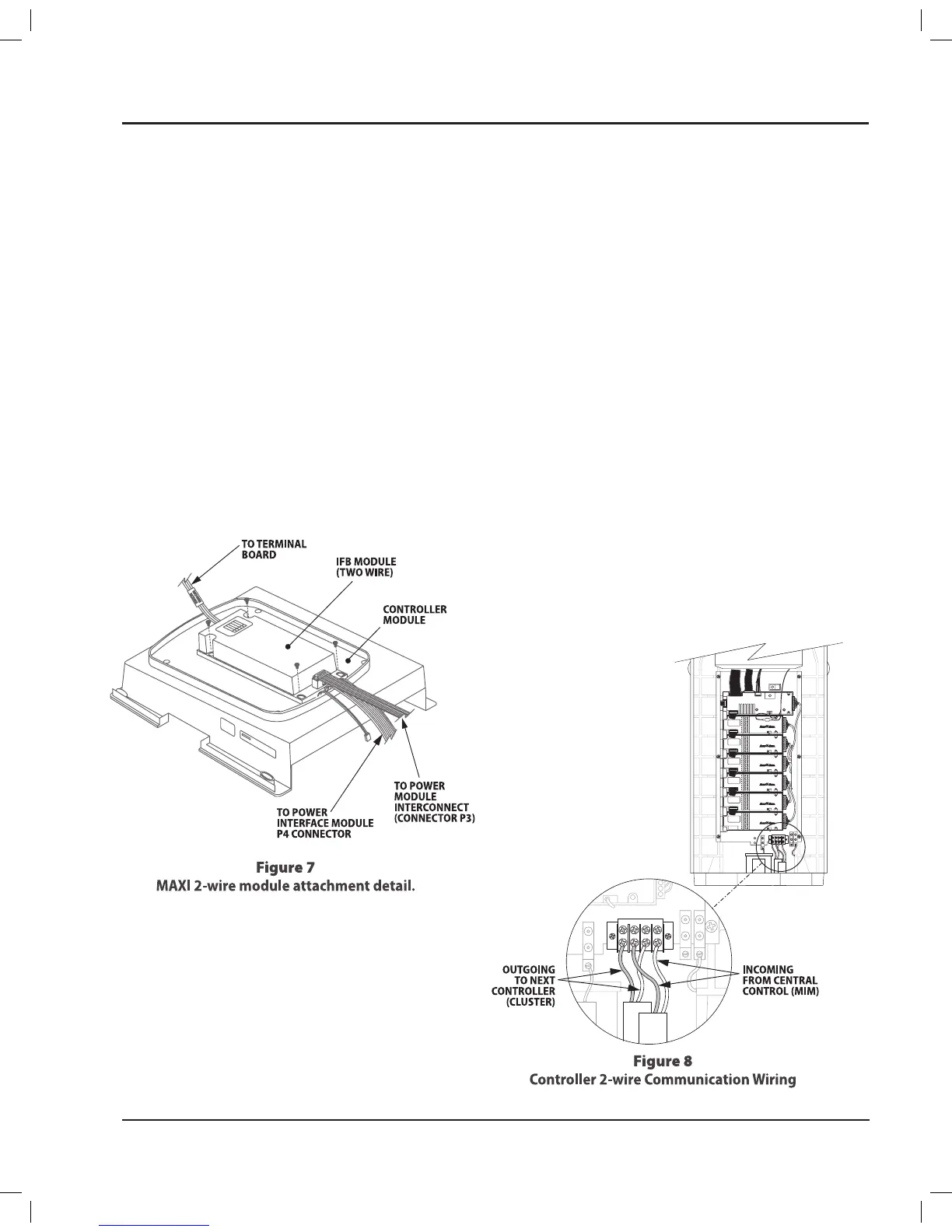
The Maxi 2-wire board mounts under the control
module (face panel) of the basic PAR+ES controller�
Remove the four screws from the face panel bezel
1.
(not the interior face panel screws) and lift out the
control module�
Use four #4-40 machine screws to attach the
2.
MAXI 2-Wire module to the bottom of the control
module, as shown in Figure 7�
Cable Connections
Connect the 10-pin ribbon cable from the connector
on the left end of the MAXI 2-Wire board to the 10-pin
connector on the left end of the Power Interconnect
Module�
2-Wire Path Connections
On the lower front of the controller is a 4-terminal
connection block (see Figure 8)�
Connect the HOT (red) wire of the 2-wire
1.
communication path to terminal #4 (lower right
terminal)�
Connect the COM (black) wire of the 2-Wire
2.
communication path to terminal #2�
Connect the HOT (red) wire of the 2-Wire
3.
communication path going to the next controller
to terminal #3�
Connect the COM (black) wire of the 2-Wire
4.
communication path going to the next controller
to terminal #1 (bottom left terminal)�
NOTE:
!
If sharing only one MSP-1 among a
cluster of controllers, then splice the black
and red wires on the EQUIP side of the
MSP-1� Connect one set of wires to the green
plug that connects to the 2-wire interface
board� Connect the other set of wires to the
4-terminal connecting block of the second
controller�
PAR+ES Installation Manual 7
 Loading...