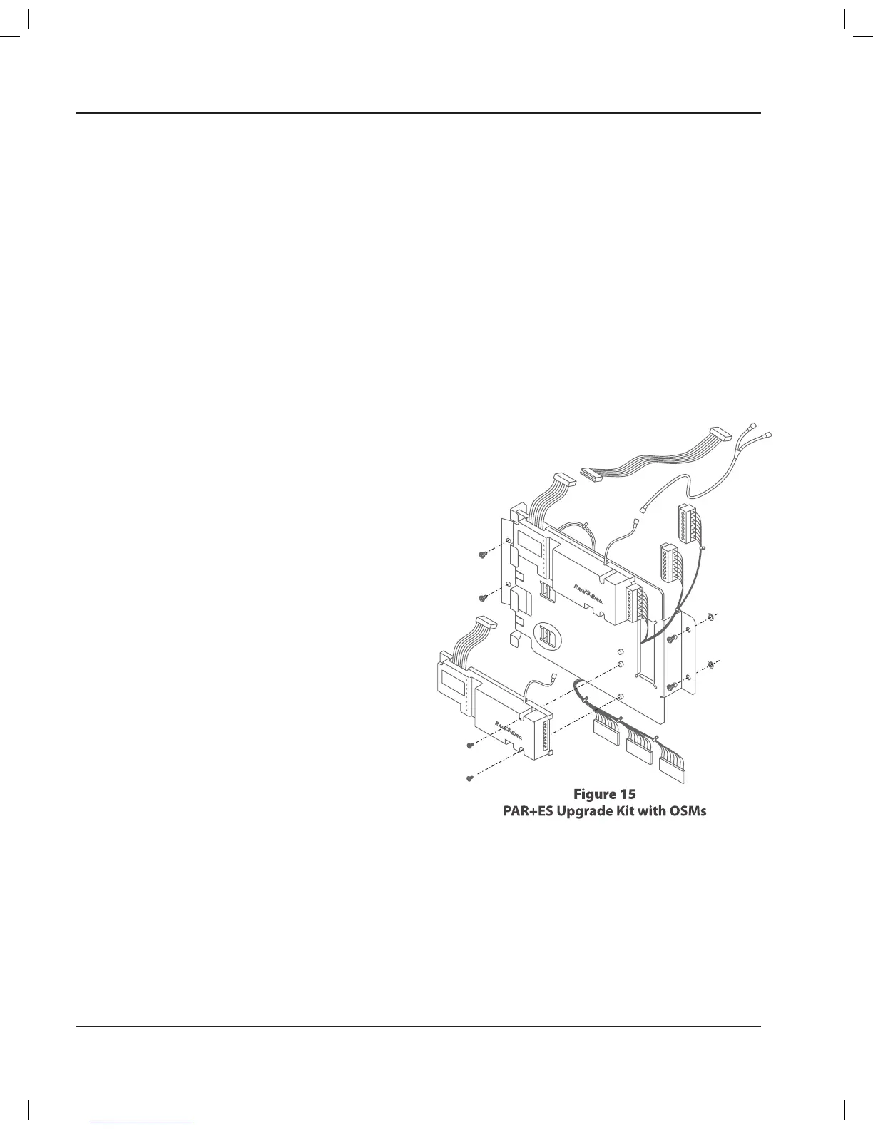
Upgrade Kit Installation
For controllers ordered with more than 48 stations,
a swing out bracket (where three 3” additional
OSMs can be installed), terminal strip, power and
communication cables and the appropriate OSMs are
pre-installed� If ordered with fewer than 48 stations, an
Upgrade Kit will be required for the expansion of the
PAR+ES controller to 72 stations (see Figure 15)� The
Upgrade Kit includes a swing-out bracket, terminal
strip, power and communication cables�
Installation of Swing-out Bracket
To install the swing-out bracket, using two #10-32 1.
screws, attach to the left rail, just above the first
terminal strip�
Once in place, attach the OSM(s) as described
2.
below�
Installation of Power and Ribbon Cables (for
OSM for stations 49-56)
Disconnect power cable between PIB (Power 1.
Interconnect Board) and first OSM�
Connect “Y” cable to power cable of first OSM�
2.
Connect short end of “Y” cable to the PIB, at the 3.
bottom end�
Connect the long end of the “Y” cable to the first
4.
OSM installed on the swing-out bracket�
Connect the ribbon cable to the top left opening
5.
in the PIB board� Connect the other end of the
ribbon cable to the first OSM on the swing-out
bracket by attaching to ribbon cable located at
the top left�
For second and third OSMs installed on swing-out
bracket (for stations 57-72):
Insert the 16-wire ribbon cable coming from the
6.
top of the OSM into the 16-pin connector on the
bottom left of the OSM above it�
Repeat Step 6 to connect the ribbon cable for the
7.
last OSM being installed�
Insert the power cable coming from the top right
8.
of the bottom OSM to the bottom right of the
OSM above it�
Repeat Step 8 to connect power cable for last
9.
OSM being installed�
Terminal Strip Installation
Install the third terminal strip just below the 1.
second terminal strip by using four #10-32 screws
(two at each end) and attaching to the rails�
Connect one end of harness cable (green plugs)
2.
to the corresponding OSMs for stations 49-72�
Connect the other end of harness cable to third
3.
terminal strip in the following order from left to
right (P7, P8, P9)�
Connect each stations valve wire to its appropriate
4.
terminal on the controller’s third terminal strips
(i�e�, station 49 to terminal #1, station 50 to
terminal #2, etc�) Each station can control up to
four valves�
PAR+ES Installation Manual16
 Loading...