Connect AC Power Supply
Connect AC Power
CAUTION:
F
To avoid a serious shock hazard,
make sure the primary AC power source to
the controller is OFF�
Punch out a knockout hole in the top of the
1.
junction box and run a length of conduit from
the junction box to the controller’s power supply
compartment�
Use appropriate fittings to connect the conduit
2.
to the junction box and the power supply
compartment�
Run three power wires from the power supply
3.
compartment down into the junction box (green,
black and white for 120 VAC installations; green
black and red or other appropriately identified
hot-wire for 220-240 VAC installation)�
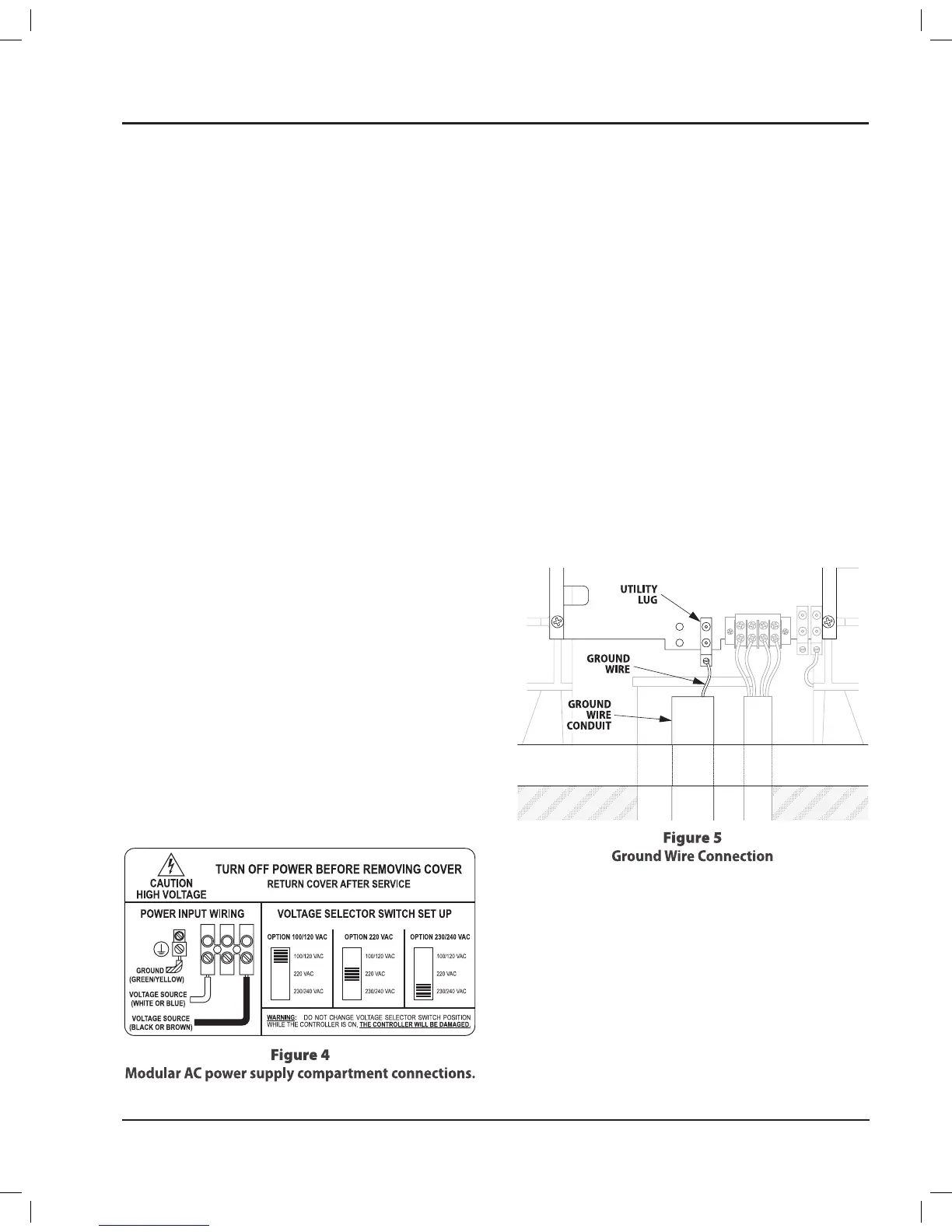
Attach the power wires to the modular snap-in
4.
connector in the power supply compartment, as
shown in the diagram on the power supply access
cover (see Figure 4)�
Connect the utility ground to the ground lug
5.
on the left side of the wiring compartment (see
Figure 5)�
Use the 3-position selector switch to choose
6.
correct voltage option for your installation (default
voltage setting is 220 VAC)�
NOTE:
!
Select the correct voltage before
turning on AC power� If the switch position is
changed after applying power, the controller
will be damaged�
NOTE:
!
In 240 VAC the power wire are colored
red/black or red/blue�
Connect Power Wires and Surge
Arrestor Wires
In the junction box, connect the AC power wires 1.
(black, white, and green) as shown in Figure 3�
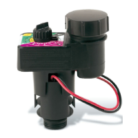
Wire the two black surge arrestor lead wires into
2.
the controller’s 120, 220, or 240 VAC power wiring�
Connect one of the two black surge arrestor lead
wires to the HOT (black) power wire�
NOTE:
!
Use only double-crimp style wire nuts
approved by local regulations for all PAR+ES
wiring connections�
Connect the other black surge arrestor lead wire
3.
to the NEUTRAL (white) power wire�
NOTE:
!
If using a 220/240 volt system, the
other black surge arrestor lead should go to
the other HOT (red or blue) power wire�
Connect the white surge arrestor ground wire to
4.
one of the controller’s copper grounding lugs�
NOTE:
!
Each controller location or cluster of
controllers requires a Controller Grounding
System to protect your controller(s) from
lightning damage� Refer to the manual
Appendix for details on installing an
appropriate grounding system for your
location�
PAR+ES Installation Manual 5
 Loading...