Before Pouring Concrete Pad
Position a 1” sweep “ell” for the 120, 220, or 240 1.
volt power wires� If installing multiple controllers
on the same pad, position another 1” sweep ell
to carry power wires to the other controllers (see
Figures X and Y for proper sweep details)�
Position a 1” sweep ell for the 2-wire
2.
communication wires (for 2-wire systems only)�
If installing multiple controllers on the same pad,
place another 1” sweep ell to carry communication
wires to the other controllers�
Position one 4” ell for the valve output wiring, valve
3.
common wires, Maxi Wire (decoder controller
installation), master valve wiring, etc�
NOTE:
!
Decoder Controllers only require a 1
1/2” sweep ell for valve wire path(s), master
valve wiring, ground wire, etc�
Run all power wires, communication wires, and
4.
field wiring through their appropriate conduits�
Pour the Concrete Pad and Mount
the Pedestal
Pour the concrete pad around the properly 1.
positioned sweep ells�
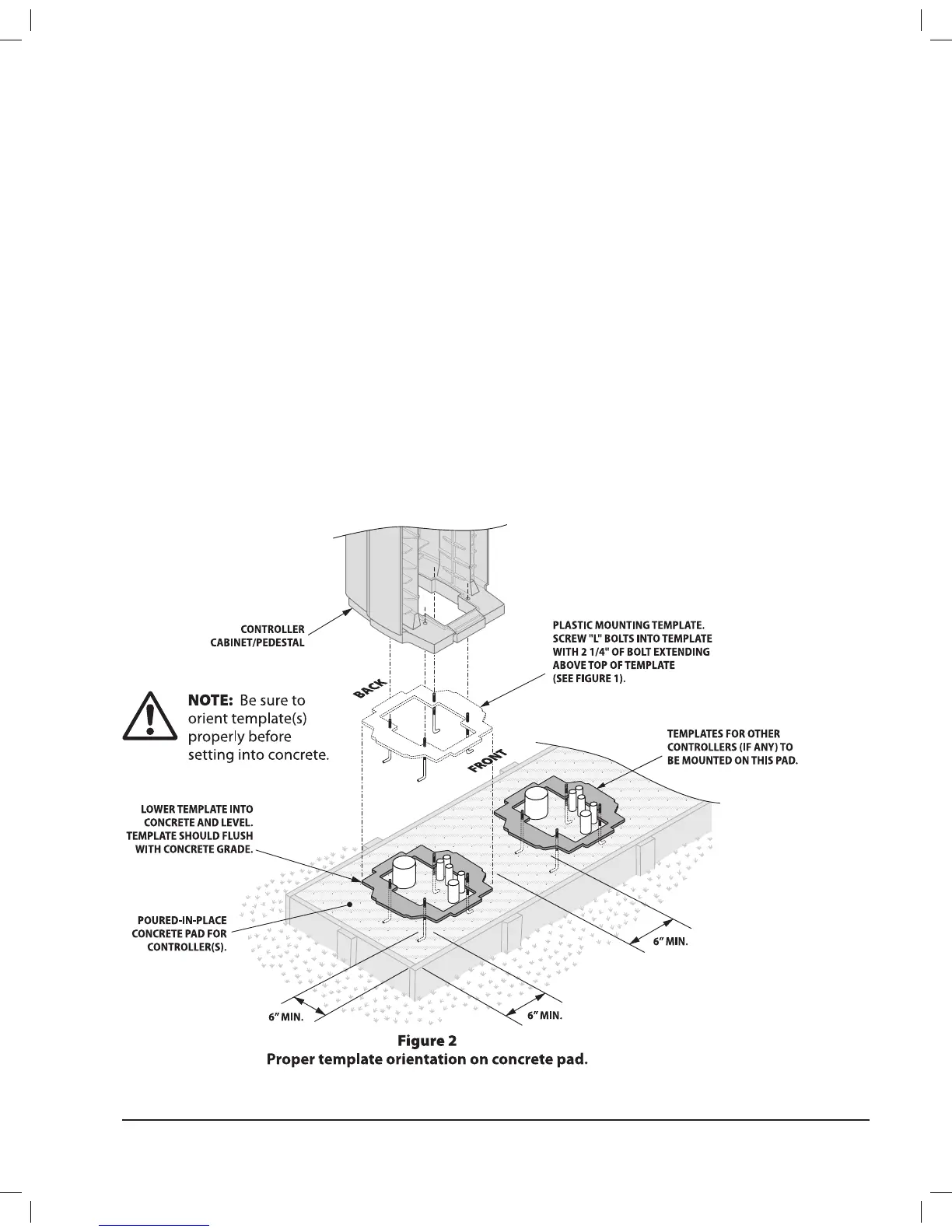
Lower the mounting template onto the pad,
2.
setting the L-bolts into concrete as shown in
Figure 2� Make sure the template is level and
properly oriented before setting it into concrete
at concrete’s grade� Make sure the L-bolts extend
true vertical from the pad�
If installing multiple controllers, position the
3.
mounting templates for the other controllers�
Make sure to maintain a minimum 6” clearance
distance between controllers�
After the concrete hardens, remove the four
4.
exposed nuts from the L-bolts�
Lower the controller pedestal onto the L-bolts in
5.
the template� Place a split-ring washer on each
bolt and use the stainless-steel nuts to bolt the
controller pedestal securely to the concrete pad�
PAR+ES Installation Manual 3
 Loading...