Raisecom
iTN8600-I (A) Product Description
Raisecom Proprietary and Confidential
Copyright © Raisecom Technology Co., Ltd.
Figures
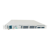
Figure 1-1 Front appearance of the iTN8600-I-XT4D-AC .................................................................................... 2
Figure 1-2 Front appearance of the iTN8600-I-XT4D-DC .................................................................................... 2
Figure 1-3 Appearance of the iTN8600-I-XT4D-AC and iTN8600-I-XT4D-DC .................................................. 2
Figure 1-4 Typical point-to-point application ........................................................................................................ 4
Figure 1-5 Typical point-to-point WDM application ............................................................................................. 5
Figure 1-6 Typical ring network application .......................................................................................................... 6
Figure 2-1 Hardware structure ............................................................................................................................. 12
Figure 2-2 Software structure ............................................................................................................................... 13
Figure 3-1 Appearance of the iTN8600-I-XT4D .................................................................................................. 15
Figure 3-2 Panel of the DC power supply ............................................................................................................ 19
Figure 3-3 Panel of the AC power supply ............................................................................................................ 21
Figure 3-4 Panel of the fan ................................................................................................................................... 23
Figure 5-1 LC/PC fiber connector ........................................................................................................................ 42
Figure 5-2 MPO fiber connector .......................................................................................................................... 43
Figure 5-3 MPO-LC branch optical fiber jumper ................................................................................................. 44
Figure 5-4 Ethernet cable ..................................................................................................................................... 45
Figure 5-5 Wiring of the straight-through cable ................................................................................................... 46
Figure 5-6 Wiring of the 100 Mbit/s crossover cable ........................................................................................... 46
Figure 5-7 Wiring of the 1000 Mbit/s crossover cable ......................................................................................... 47
Figure 5-8 Configuration cable ............................................................................................................................ 48
Figure 5-9 DC power cable .................................................................................................................................. 48
Figure 5-10 Stripping dimensions and connector ................................................................................................. 50
Figure 5-11 European AC cable ........................................................................................................................... 50
Figure 5-12 American AC cable ........................................................................................................................... 51
Figure 5-13 Ground cable .................................................................................................................................... 52
Figure 5-14 OT terminal ...................................................................................................................................... 52
 Loading...