Figures
Figure 1-1 Networking application with the MSG1200 ......................................................................................... 2
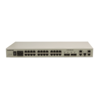
Figure 2-1 Appearance of the MSG1200................................................................................................................ 8
Figure 2-2 LEDs on the MSG1200-GEC ............................................................................................................... 9
Figure 2-3 LEDs on the MSG1200-EPON ............................................................................................................. 9
Figure 2-4 LEDs on the MSG1200-UPON ............................................................................................................ 9
Figure 2-5 Optical interface on the MSG1200 ..................................................................................................... 11
Figure 2-6 Other interfaces on the MSG1200-GEC ............................................................................................. 12
Figure 2-7 Other interfaces on the MSG1200-EPON .......................................................................................... 13
Figure 2-8 Other interfaces on the MSG1200-UPON .......................................................................................... 13
Figure 2-9 Buttons on the MSG1200 ................................................................................................................... 14
Figure 2-10 LC/PC connector .............................................................................................................................. 16
Figure 2-11 SC/PC connector ............................................................................................................................... 17
Figure 2-12 FC/PC connector .............................................................................................................................. 17
Figure 2-13 Ethernet cable ................................................................................................................................... 18
Figure 2-14 Line order of the straight-through cable ........................................................................................... 19
Figure 2-15 Line order of the 100 Mbit/s crossover cable ................................................................................... 20
Figure 2-16 Line order of the 1000 Mbit/s crossover cable ................................................................................. 20
Figure 2-17 Telephone cable ................................................................................................................................ 21
Figure 4-1 Installation procedure ......................................................................................................................... 29
Figure 4-2 Installing the MSG1200 on the wall ................................................................................................... 30
Figure 4-3 Connecting other devices .................................................................................................................... 31
Figure 4-4 Removing the fiber cover ................................................................................................................... 32
Figure 4-5 Installing the SFP optical module ....................................................................................................... 32
Figure 4-6 Connecting fibers (1) .......................................................................................................................... 33
Figure 4-7 Connecting fibers (2) .......................................................................................................................... 33
Figure 4-8 Installing the fiber cover ..................................................................................................................... 34