GB-F-NL-18
GB
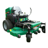
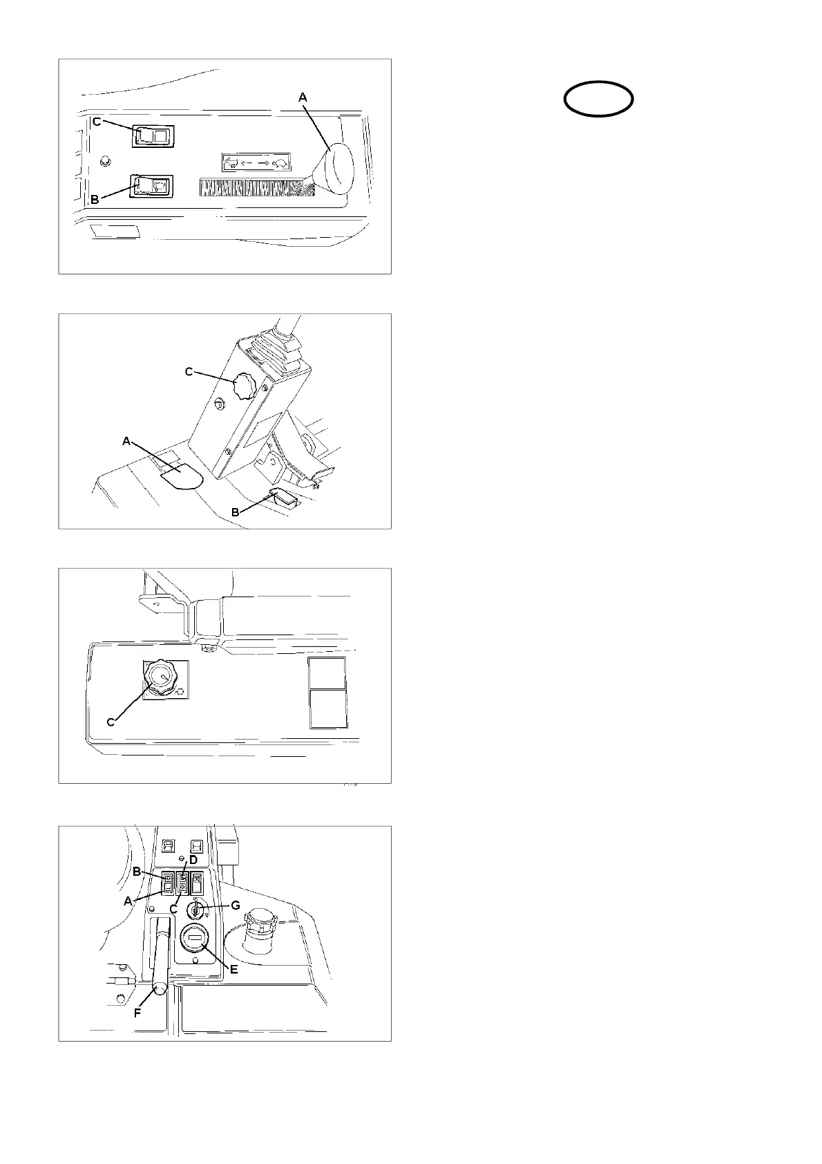
Fig.6
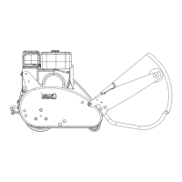
Fig.7
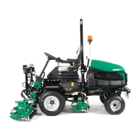
Fig.8
THROTTLE CONTROL LEVER (A Fig.6)
The lever should be moved towards the front of the
machine to increase the engine speed and towards
the rear of the machine to decrease the engine speed.
NOTE: Engine should be used at full speed.
CROSS CUT LATCH (B Fig.7)
The cross cut latch stops the front cutting units fully
lifting allowing quicker turn round when cutting to an
edge and is permanently engaged. To lift the front
cutting units fully for transport the cross cut latch
release foot pedal should be depressed before the
cutting units are raised and not released until the
cutting units are fully raised.
STEERING WHEEL RAKE ADJUSTMENT (C Fig.7)
The steering wheel is adjustable for rake. The
clamping wheel is situated on the side of the steering
support cover. To adjust turn the clamping wheel
anticlockwise to release the pivot, move the steering
column as required and lock in position by turning the
clamping wheel clockwise.
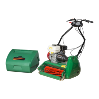
PARKING BRAKE LEVER (F Fig.9)
The parking brake lever has an over centre
mechanism. The brakes are applied with the lever in
the up position and released with the lever in the down
position.
CUTTING UNIT SPEED CONTROL (C Fig.8)
The speed of the the cutting cylinders may be
controled by the hand wheel to the rear of the right
hand control panel. This may be varied between a
maximum of 1100rpm and a minimum 0f 0rpm. To
increase the speed the hand wheel should be turned
anticlockwise.
CUTTING CYLINDER DRIVE SWITCH (Fig.6)
NOTE: The operation of the foot operated switch does
not apply to machines in the USA.
There are two switches to control the cutting cylinder
drive system.
the first (B Fig.6) is the drive enable switch. To start
the machine the switch must be off, the green indicator
lamp will not be lit.
Once the machine is running the switch can be
operated, the indicator lamp is illuminated to show the
drive system is enabled.
A second switch (C Fig.6) selects either forward
rotation for cutting or reverse rotation for backlapping
or clearing the cutting cylinder. When reverse rotation
is selected the red indicator lamp will be illuminated.
Fig.9