Chapter 2
6 AccuFlow™ and AccuFlow HP™ Installation & Operation Manual
Standard AccuFlow™ Kit Contents
Please review the following tables for components, parts, and fittings which should have been supplied with the
Raven AccuFlow system. It may be necessary to order some components of the AccuFlow system separately.
Before beginning assembly and installation, verify that all required components have been purchased.
Note: AccuFlow systems will require appropriate flow cabling to connect to the Raven control console.
Contact a local Raven dealer for assistance and information.
To provide the most responsive control of anhydrous ammonia applications when using a multi-
section tool bar, a check valve assembly (P/N 063-0173-030, ordered separately) should be
installed if the section on/off valves are mounted next to the distributor manifolds. Refer to the
diagrams provided in Chapter 3, Standard AccuFlow™ Installation, for location. Contact a local
Raven dealer for more information.
See Chapter 9, System Diagrams, for detailed diagrams and system connections.
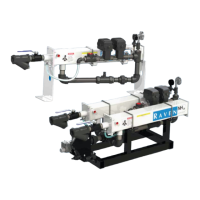
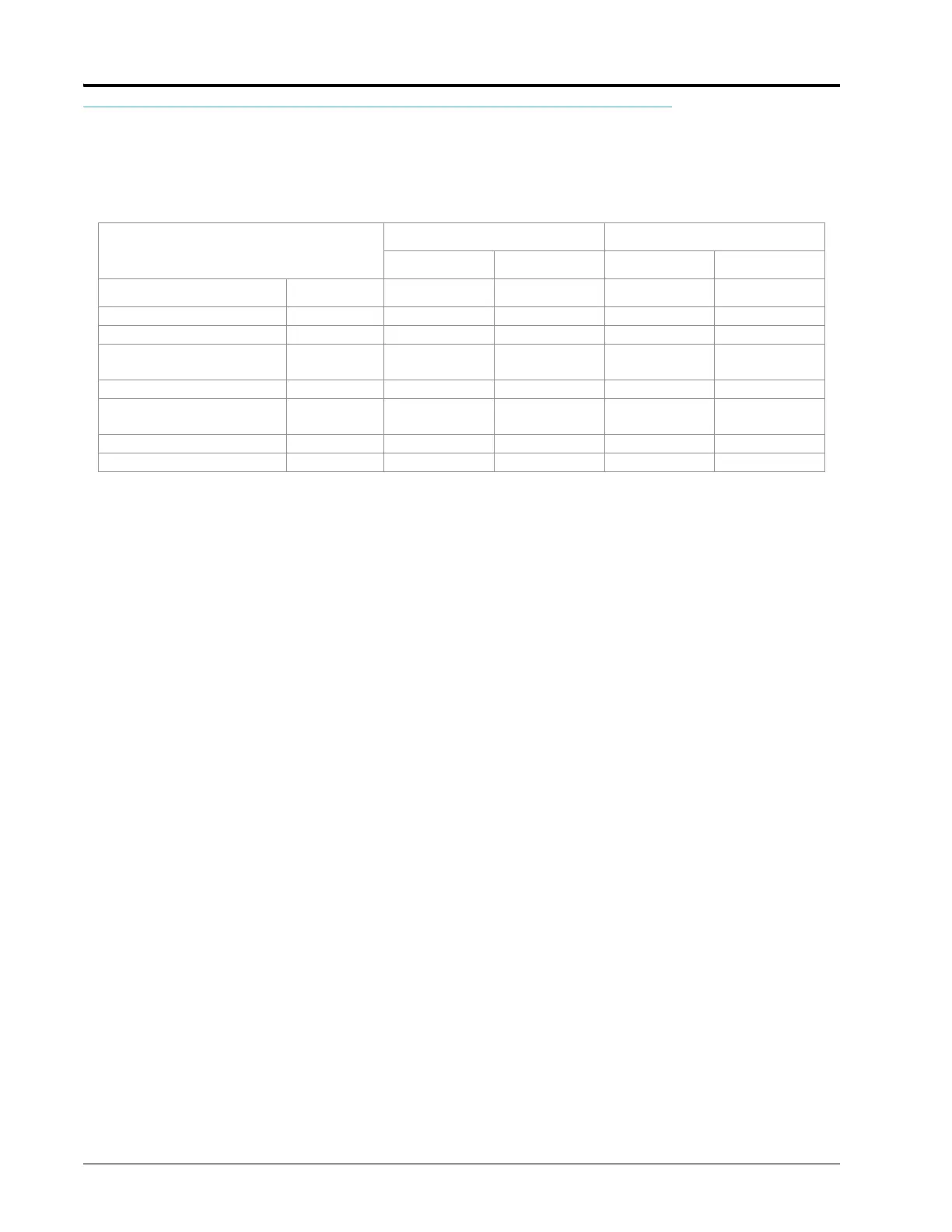
AccuFlow
Systems and Kits
Single Cooler Kits Dual Cooler Systems
Two Valve Kit Fast Valve Kit Two Valve Kit Fast Valve Kit
Components P/N 117-0171-384 117-0171-386 117-0171-387 117-0171-389
AccuFlow Super Cooler 063-0173-314 1 1 2 2
Fittings for Assembly 117-0171-385 1 1 1 1
Fittings for Assembly, Dual
Cooler
117-0171-388 1 1
Flow Meter, RFM 60S 063-0171-666 1 1 1 1
Valve,
1-1/4” NPT Control
063-0173-202 1 1
Valve, 1-1/4” NPT On/Off 063-0173-203 1 1
Valve, 1-1/4” NPT Fast Valve 063-0173-204 1 1