EasyManua.ls Logo

Raytheon Anschütz STD 22 Compact GYRO COMPASS User Manual

Raytheon Anschütz STD 22 Compact GYRO COMPASS
50 pages
To Next Page IconTo Next Page
Page #1 background imageLoading...
Page #1 background image
Raytheon Anschütz GmbH
Postfach 1166
D -- 24100 Kiel
Germany
Tel+49--431--3019--0
Fax+49--431--3019--501
Email Service@raykiel.com
www.raytheon --anschuetz.de
3646/110--233.DOC010102 Edition: May 20, 2005
Revision: July 1, 2005
Revision: Sept. 1, 2005
Revision: Feb. 17, 2006
STD 22 Compact GYRO COMPASS
and
STD 22 GYRO COMPASS
Type 110 --233
Operator manual

Other manuals for Raytheon Anschütz STD 22 Compact GYRO COMPASS

Question and Answer IconNeed help?

Do you have a question about the Raytheon Anschütz STD 22 Compact GYRO COMPASS and is the answer not in the manual?

Raytheon Anschütz STD 22 Compact GYRO COMPASS Specifications

General IconGeneral
ManufacturerRaytheon Anschütz
TypeGyro Compass
ModelSTD 22 Compact
Power Supply24 V DC
Operating Temperature Range-15 °C to +55 °C
Storage Temperature Range-25 °C to +70 °C
Roll and PitchUp to ±45°
Repeatability±0.1°
VibrationIEC 60945
Shock15 g / 11 ms
Communication InterfacesNMEA 0183
Power ConsumptionApprox. 60 W (in operation)
HumidityUp to 95% relative humidity, non-condensing

Summary

Safety Information

Maintenance and Repair Safety

Work should only be performed by trained staff following safety regulations.

Operational Precautions

Wait 15 mins after shutdown; ensure display visibility; handle warnings promptly.

SOLAS Gyro Compass Requirement

Ships >500 GT need operational gyro compass; avoid switching off during voyages.

Operational Notes and Updates

STD 22 Compact Gyro Compass Optional Features

Quick Settling Operator Unit

Reduces settling time to approx. 1 hour by storing last heading.

Quick Settling Usage Conditions

Valid only if ship's heading is unchanged between power cycles.

AC/DC Converter 121-062

Additional Output Box 146-103

Anschütz Gyro Compass Standard 22 System Components

Manufacturer's Declaration of Conformity

General

Compass Purpose and Application

Navigation aid determining north bearing, unaffected by magnetic field.

System Application Distinction

Differentiates stand-alone vs. system component applications.

System Input/Output Comparison

STD 22 Compact Gyro Compass

Speed Error Correction (SEC)

Automatically corrects latitude error using speed and latitude data.

Quick Settling Operator Unit (Option)

STD 22 Compact Output Interfaces

STD 22 Compact Input Interfaces

STD 22 Compact Gyro Compass - Scope of Supply

Quick Settling Operator Unit

Quick Settling Functionality

Reduces settling time to approximately one hour.

Quick Settling Usage Conditions

Not usable for initial installation or if heading changed.

AC/DC Converter, 121-062

Additional Output Box 146-103

STD 22 Gyro Compass System Configuration

System Requirements

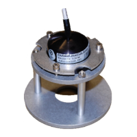
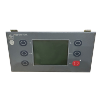
Requires Operator Unit (130-613) and Distribution Unit (138-118).

STD 22 Gyro Compass Interfaces

STD 22 Gyro Compass - Scope of Supply

AC/DC Converter, 121-062

Technical Data

Mechanical Data

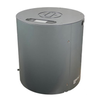
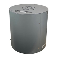
Provides height, diameter, weight, and enclosure type.

Electrical Data

Specifies supply voltage and current consumption.

General Technical Data

"Quick Settling” Function

Reduces the settling phase to approximately 1 hour.

Speed Error Correction

Automatic course correction based on speed and latitude.

Indicator Precision

Details display resolution and course precision.

Controls and Indicators on the Gyro Compass

Digital Indication Overview

Describes display indications for course, status, warnings, and errors.

Operating Elements on the Compass

Switching on the STD 22 Compass

Heating Stage

First 30 mins, indicated by 'h', no course output.

Settling Stage

Follow-up system activates at 45°C, accuracy improves over 4-5 hours.

Quick Settling Option Impact

Reduces settling phase to one hour with +/-3° precision.

Indications during the heating stage

Indications on the compass during the settling stage

Overview of indications (digital display) during operation

Heading correction

Alignment error

Error occurs if compass zero line doesn't match ship's pre-alignment.

Procedure for setting the compass zero (A-error)

Step-by-step guide to correct alignment error using buttons and DIP switch.

Speed error

Speed Error Correction on STD22 Compact

Automatic correction requires GPS/Pulse Log data.

Speed Error Correction on STD22 Gyro Compass

Allows manual input of speed and latitude for correction.

Example of Course Calculation

Example of a Bearing

Speed error table

Warning signals

Warning Indication

Flashing decimal point on display indicates pending warning.

Warning Impact on Course Display

Course display is unaffected, except for 'Voltage cut-off'.

Warnings, their causes, and what to do

Warning Identification

Lists 5 warnings (1-5) displayed via buttons B38/B39.

How to display the warning messages

Warning 1 "Fan failure"

Warning 2 "Heater failure"

Warning 3 "Supporting liquid > 60°C."

Warning 4 "Supporting liquid level too low"

Warning 5 "Voltage cut-off"

Digital display for “Voltage cut-off"

Alarm signalling (in the event of an error)

Error Indication

Displays 'Erro' and an error code when internal PC-board fails.

Operating elements on the compass (after removing the cover)

Error Group and Comment List

Switching off the Gyro Compass

Cautionary Notes for Shutdown

Emphasizes trained personnel and waiting period before interior access.

Maintenance

Supporting Liquid Replacement Schedule

Replace supporting liquid and O-rings every 18 months.

Related product manuals