13
RC GROUP - 149_ItEn.0102
0
1
2
3
4
5
6
3
2
1
J14
A
B
M
C
3
2
1
J15
1
4
32
5
35
75
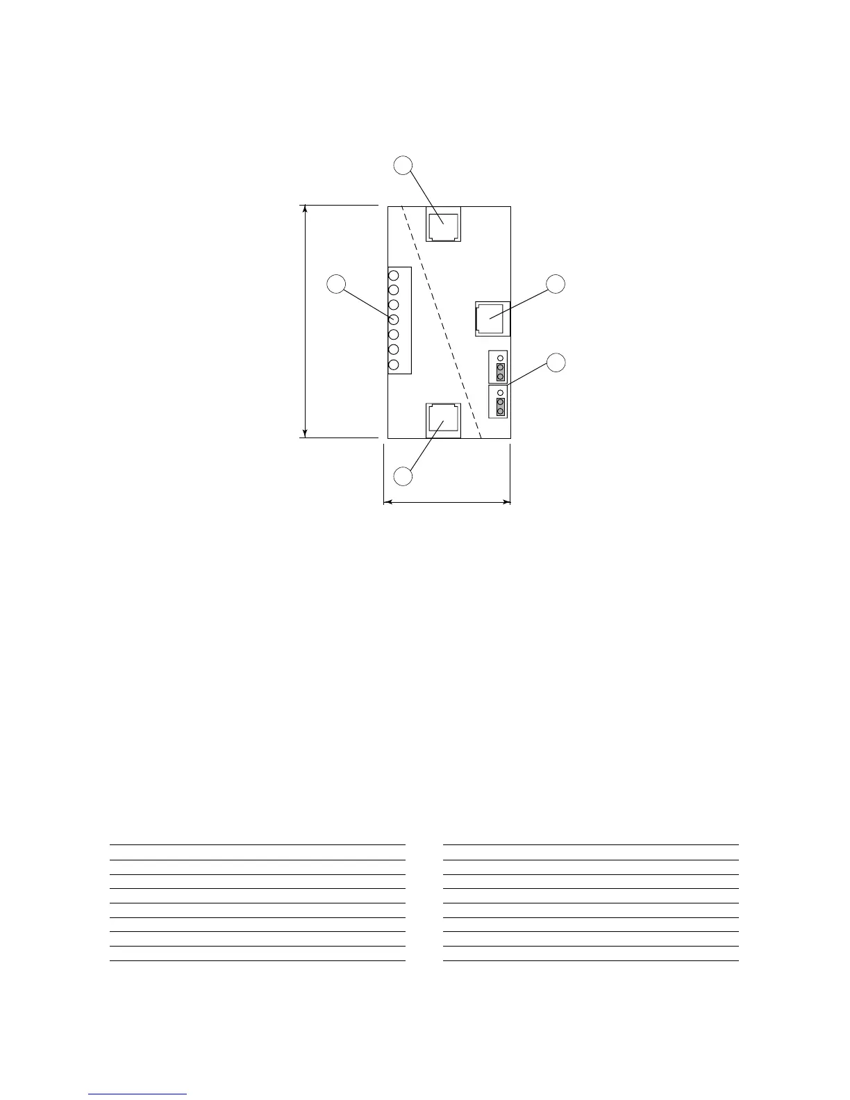
"T" BOARD
This board is essentially a T-derivator used for "T" remote
terminal connection.
As shown in the picture, the board
is equipped with 3 telephone con-
nectors and terminals.
By using the "T" board for con-
nection to a Remote Terminal, it
is necessary to set the J14-J15
jumpers on 1-2 position. In this
way the electrical feeding is avail-
able on all connectors (A-B-C-
M).
1. Available telephone connector
for Board "A" or "T" Remote Ter-
minal or unit Terminal connec-
tion.
2. Available telephone connector
for Board "A" or "T" Remote Ter-
minal or unit Terminal connec-
tion.
3. Terminals for "T" board on "T"
Remote Terminal.
4. Available telephone connector
for Board "A" or "T" Remote Ter-
minal or unit Terminal connec-
tion.
5. Setting jumpers.
JUMPERS SETTING J14 - J15
Set 1 - 2
The three telephone connectors A - B - C and the screw
connector M are linked in parallel. The power supply is
available on all connectors.
Set 2 - 3
The electrical feeding of B - C connectors is separate from
the one of A - M connectors.
The LAN network is not interrupted among the several
connectors.
In case the two jumpers J14 - J15 are set in different
position, the T-derivator does NOT work.
Conn.M Conn.A-B-C
0 == Braiding of shielded wire
1 1 +VRL = 30Vdc
2 2 GND
3 3 Rx- / Tx-
4 4 Rx+ / Tx+
5 5 GND
6 6 +VRL = 30Vdc
When a shielded cable is used, the metallic case of the T
derivator must be earthed.
SCHEDA "T"
Questa scheda è essenzialmente un derivatore a T e trova
impiego nel collegamento al termi-
nale remoto "T".
Come indicato in figura la scheda è
equipaggiata con 3 connettori tele-
fonici e con una morsettiera.
Utilizzando la scheda "T" per il
collegamento al Terminale Remo-
to è necessario predisporre i pon-
ticelli J14 - J15 in posizione 1-2 per
rendere l'alimentazione elettrica
diponibile su tutti i connettori (A-B-
C-M).
1.Connettore telefonico disponibi-
le per collegamento Board "A" o
Terminale Remoto "T" o Termi-
nale a bordo macchina.
2.Connettore telefonico disponibi-
le per collegamento Board "A" o
Terminale Remoto "T" o Termi-
nale a bordo macchina.
3.Morsettiera per connessione
scheda "T" del Terminale Remo-
to "T".
4.Connettore telefonico disponibi-
le per collegamento Board "A" o
Terminale Remoto "T" o Termi-
nale a bordo macchina.
5.Ponticelli di settaggio.
Fig. 6
SETTAGGIO PONTICELLI J14 - J15
Posizione 1 - 2
I tre connettori telefonici A - B - C ed il connettore a vite M
sono posti in parallelo. L'alimentazione è disponibile su
tutti i connettori.
Posizione 2 - 3
L'alimentazione elettrica presente sui connettori B - C è
separata da quella presente sui connettori A - M.
La connessione LAN non viene interrotta tra i vari connet-
tori.
Nel caso i due ponticelli J14 - J15 siano posizionati in
modo differente il derivatore NON funziona.
Conn.M Conn.A-B-C
0 == Calza cavo schermato
1 1 +VRL = 30Vdc
2 2 GND
3 3 Rx- / Tx-
4 4 Rx+ / Tx+
5 5 GND
6 6 +VRL = 30Vdc
Quando si usa un cavo schermato il contenitore metallico
del derivatore deve essere collegato a terra.
MP2000 AIR CONDITIONERS
Sistema di controllo a microprocessore per condizionatori d'aria •
Air conditioners microprocessor control system