RC GROUP - 149_ItEn.0102
8
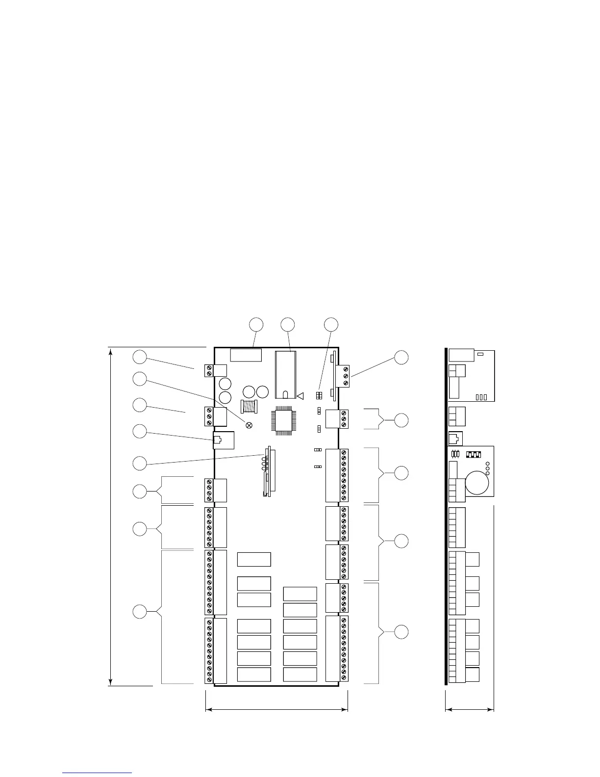
SCHEDE A MICROPROCESSORE - BOARD "A" E "B"
Il sistema di controllo può essere costituito da due schede
elettroniche; la BOARD "A" e la BOARD "B".
La BOARD "A" è la scheda principale ed è dotata di set di
morsetti estraibili necessari alla connessione verso i di-
spositivi controllati (ad esempio: valvole, compressori, ven-
tilatori, ecc.).
Il programma di gestione è memorizzato su eprom mentre
i parametri impostati sono memorizzati su uno speciale
componente elettronico (Eeprom), che consente il mante-
nimento dei dati anche in caso di mancanza di alimenta-
zione (senza il bisogno di una batteria di mantenimento).
La scheda BOARD "A" permette anche la connessione
alla rete locale LAN costituita da più schede e più termina-
li ed il collegamento verso la linea seriale di supervisione/
teleassistenza secondo lo standard RS485 e protocollo di
comunicazione RC-com.
Scheda BOARD "B" è identica alla precedente ed è dota-
ta di set di morsetti estraibili per la remotizzazione dei sin-
goli allarmi e la gestione di alcuni componenti nelle unità
con doppio circuito frigorifero.
Fig. 1
MICROPROCESSOR BOARDS - BOARD "A" AND "B"
The control system can be fitted with two electronic cards;
BOARD "A" and BOARD "B".
BOARD "A" is equipped with a set of plug-in connectors
necessary to connect the board to the controlled de-
vices (e.g. valves, compressors, fans, etc.).
The program is written in the eprom, while the set
parameters are permanently stored (even in case of
power failure) into a special electronic component named
Eeprom.
The BOARD "A" can be linked to a LAN local network,
made by more boards and terminals, or to a supervi-
sory/telemaintenance system via serial line through the
RS485 standard and the new RC-com communication
protocol.
BOARD "B" is equal to the previous one and is equipped
with a set of plug-in connectors for alarms remotization
and for the management of same components in unit with
double cooling circuit.
1
J17
1
1
1
J20
J22
1
J24
1
J6
1
J5
1
J4
1
J3
1
J2
1
J1
RS485
J15
J29
J9 J8
J21
J19
G
G0
J11
GND
RX/TX-
RX/TX+
ID11-230Vac
ID11-24Vac
ID11-R
-----------
ID12-R
ID12-24Vac
ID12-230Vac
NO8
C8
------
NO7
C7
------
NO6
C6
------
NO13
C13
C3
NO3
------
C4
NO4
------
C5
NO5
------
C12
NO12
C1
NO1
------
C2
NO2
IDCM1
ID5
ID4
ID3
ID2
ID1
IDCM2
ID10
ID9
ID8
ID7
ID6
B6
AVSS
B5
B4
AVSS
B3
B2
AVSS
B1
B8
+24Vcc
B7
NO11
C11
NC11
------
NO10
C10
NC10
------
NO9
C9
NC9
VG0
VG1
Y1
Y0
321
J14
321
3
2
1
3
2
1
3
2
1
J28
3
2
1
K11
FUSE
K10
K9
K8
K7
K6
K13
K3
K2
K1
K4
K5
K12
1
2
16 15
13
12
3
4
5
7
8
6
11
10
9
14
131
292
38
MP2000 AIR CONDITIONERS
Sistema di controllo a microprocessore per condizionatori d'aria •
Air conditioners microprocessor control system