LIFTLOG 1000 – INSTALLATION AND CALIBRATION
12
2. Installation
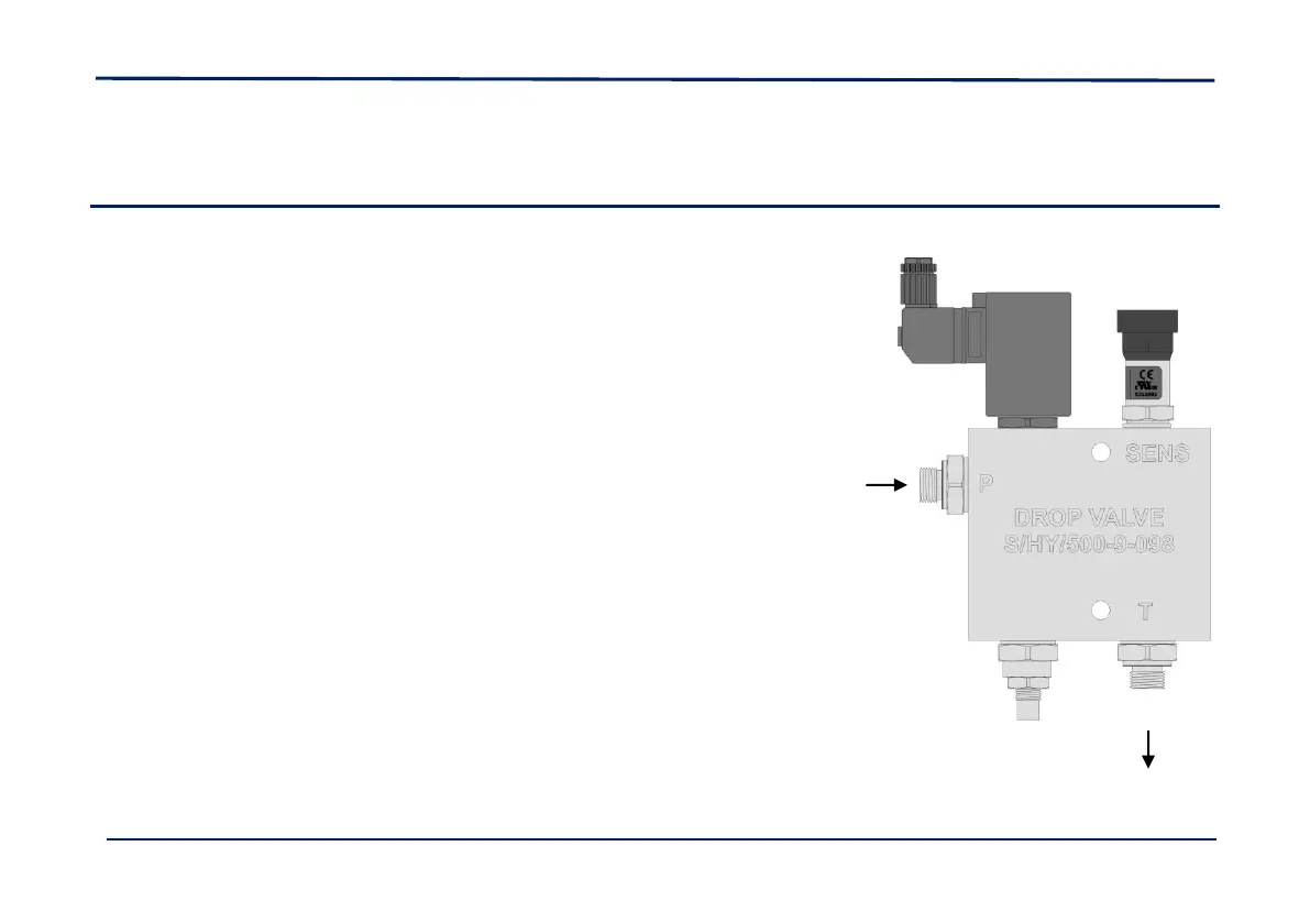
2.1 Drop Valve / Pressure Sensor
Before mounting the valve, fit the pressure sensor to the
valve body using the ¼” “Dowty” seal washer supplied.
Wherever possible, choose a mounting position where it will
be afforded the best protection from the elements. The valve
can be mounted in any orientation, but leaving the flow
adjustment screw accessible.
The drop valve pressure port marked 'P' (Pressure) should be
connected into the lift cylinder return line at a suitable
location, using the appropriate fittings (figure 1).
The drop valve return port marked 'T' (Tank) should be
connected into the hydraulic tank return line from the spool
valve block, using the appropriate fittings (Figure 1).
NOTE: Use PTFE sealing tape for low pressure fittings.
 Loading...