LIFTLOG 1000 – INSTALLATION AND CALIBRATION
18
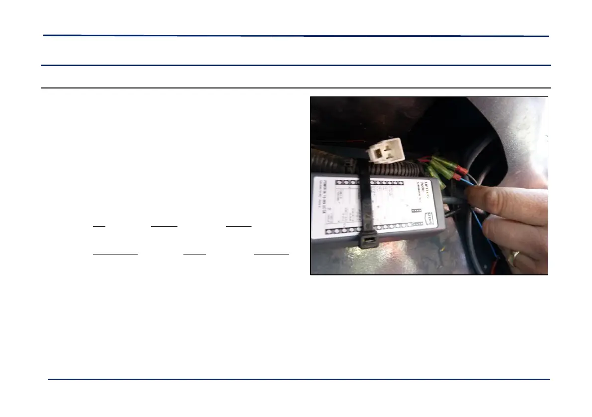
2.4 Electrical
2.4.1 Junction Box
The Junction Box or "Terminator" as it is also known, provides
for connecting the 18-core head unit cable, all sensors and
the power supply.
The Terminator is not sealed. It must be located where it will
be protected from EXCESSIVE MOISTURE AND DIRT
Cable-tie the cables entering the end of the box to the PCB.
The Base Moulding can be mounted using the screws
provided, or can be left in-line with the cables.
Connect the head unit lead onto the PCB header
The red wire on the 10-way plug goes to pin "R" on the PCB
connector.
The orange/blue wire on the 8-way plug goes to pin "O/B" on
the PCB connector.
Locate the cable grommet onto the moulding, and cable-tie
the head unit lead onto the moulded cable saddle to provide
strain relief.
NOTE: Cable-tie the cables entering the end of the box to the PCB.
 Loading...