LIFTLOG 1000 – INSTALLATION AND CALIBRATION
21
2.5 Diagnostics
Press and select the “Diagnostics” screen from the
Setup menu
The diagnostics screens provide a visual indication of the
system inputs and status.
If you experience a problem with the weighing system, with
this screen displayed, you can verify the correct operation of
the various components.
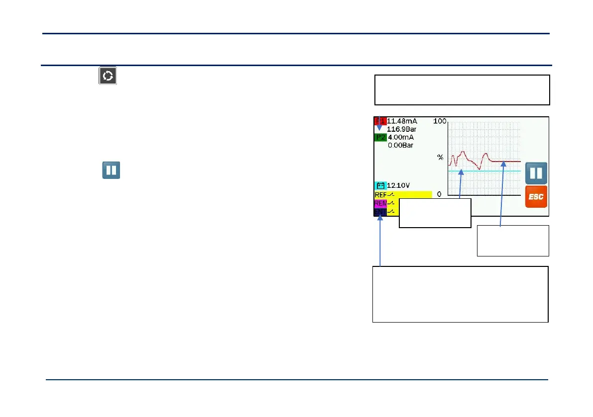
Press to freeze the real-time graphical display for the
pressure sensor and supply voltage.
NOTE: If you wish, you may take a snapshot of the screen (or any
other screen for that matter). Insert a USB stick and briefly
press the On-Off switch (the left hand rubber end piece of the
indicator). A file <ALPHAxx.BMP> will then be saved.
“P1” = Pressure Sensor output in mA and
corresponding pressure (1 bar = 14.9psi)
“REF” = Reference Sensor status
“REM” = Remote Enter Switch status
“ENT” = Remote Weight Enter Button status
Pressure
Sensor output
graph
 Loading...