EasyManua.ls Logo

RDS Technology Liftlog 1000 - Electrical Connections

Default Icon
36 pages
Print Icon
To Next Page IconTo Next Page
To Previous Page IconTo Previous Page
Loading...
LIFTLOG 1000 INSTALLATION AND CALIBRATION
20
2.4.4 Electrical Connections
Route sensor leads inside conduit back to the junction box. Cable-tie the conduit securely to existing hydraulic lines or conduits.
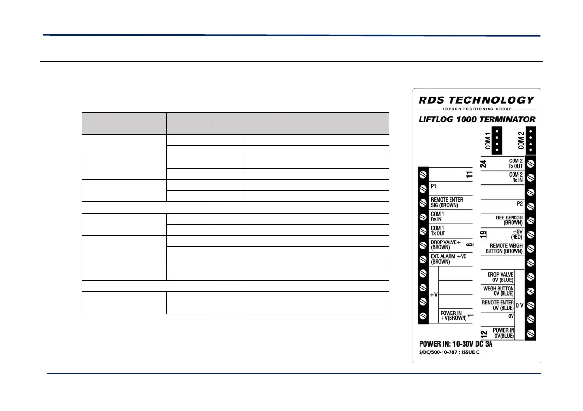
Connect the wires according to the label on the junction box lid :
Input / Output
Wire
Colour
Terminator Connection
Pressure Sensor (on
Drop valve)
Blue
10
"P1"
Brown
4
"P1 +V"
Drop Valve Solenoid
Blue
16
“DROP VALVE 0V”
Brown
6
“DROP VALVE + (BROWN)”
Reference Sensor
Blue
13
"0V"
Brown
20
"REF SENSOR (BROWN)"
Remote Enter
Switch
Blue
14
"REMOTE ENTER 0V (BLUE)"
Brown
9
"REMOTE ENTER SIG (BROWN)"
Remote Weigh
Button
Blue
15
“WEIGH BUTTON 0V (BLUE)”
Brown
18
“REMOTE WEIGH BUTTON (BROWN)”
External Alarm
Blue
13
“0V”
Brown
5
“EXTERNAL ALARM +VE (BROWN)”
Power Supply
Blue
12
“POWER IN 0V (BLUE)”
Brown
1
“POWER IN +V (BROWN)”