RealMan (Beijing) Intelligent Technology Co., Ltd.
20
Fig. 5-3 Robot arm electrical interface.
control the power supply of the robot
the blue light on once powered on
outlet the RS485、I/O etc. interface of the controller
upgrade software, import and export files
connect to ethernet devices
connect to teaching devices and remote access
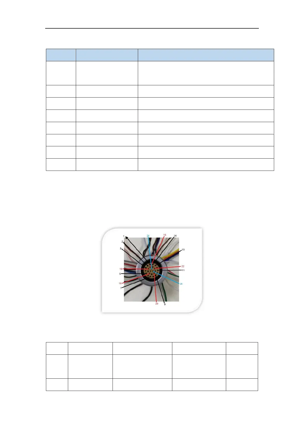
5.2 Controller I/O
There is a 26-pin connector on the robot arm controller panel. All I/Os of the robot arm
are led out from this connector. Please refer to the figure below.
Fig. 5-4 The I/O interface.
Specifically, the cable definition of the I/O interface is shown in the table below.
blue striped
brown, purple