RealMan (Beijing) Intelligent Technology Co., Ltd.
28
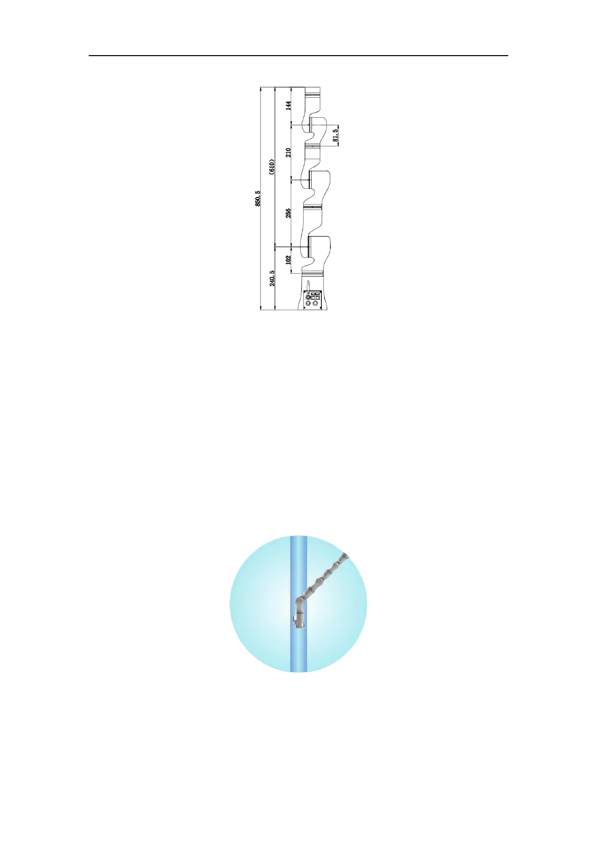
Fig. 6-1 The dimensions of robot joints.
Fig. 6-2 shows the movement range of RM65-B robot. Excluding the cylindrical space
above and below the base, the movement range of the robot is a sphere with a radius of
610 mm. When selecting the robot installation location, be sure to consider the cylinder
space above and below the robot and avoid moving the tools into the cylinder space as
much as possible. Moreover, the rotational range of each joint in practical applications
is listed as follows, i.e., rotation range of joint 1: ±180°, rotation range of joint 2: ±130°,
rotation range of joint 3: ±135°, rotation range of joint 4: ±180°, rotation range of joint
5: ±128°, and rotation range of joint 6: ±360°.
Fig. 6-2 The schematic of the movement range of the robot.
6.4 Robot Installation
When installing on the base, 4 M6 bolts are used to fix the robot body on the base. The