RealMan (Beijing) Intelligent Technology Co., Ltd.
37
Fig. 8-11 The position control panel.
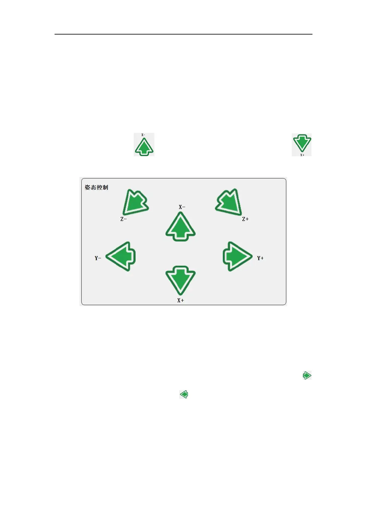
8.2.6 Pose Control
The pose of the robot arm end can be controlled based on the Base coordinate system,
the tool coordinate system (Arm_Tip) and the customized coordinate system. The user
can teach the robot end in different coordinate systems. When teaching pose, the
position of the robot arm end remains unchanged while the pose changes around the
specified coordinate axis. denotes rotating to negative x-axis direction,
denotes rotating to positive x-axis direction.
Fig. 8-12 The pose control panel.
8.2.7 Joint Control
The robot has 6 DoF. Each joint from bottom to top is named as joint 1 to joint 6, which
corresponds to the six joints of the robot. Users only need to use the joint control buttons
on the teaching software panel to control the rotation of each robotic arm joint.
denotes increasing the angle of the joint, denotes decreasing the angle of the join.
Unit: degree.