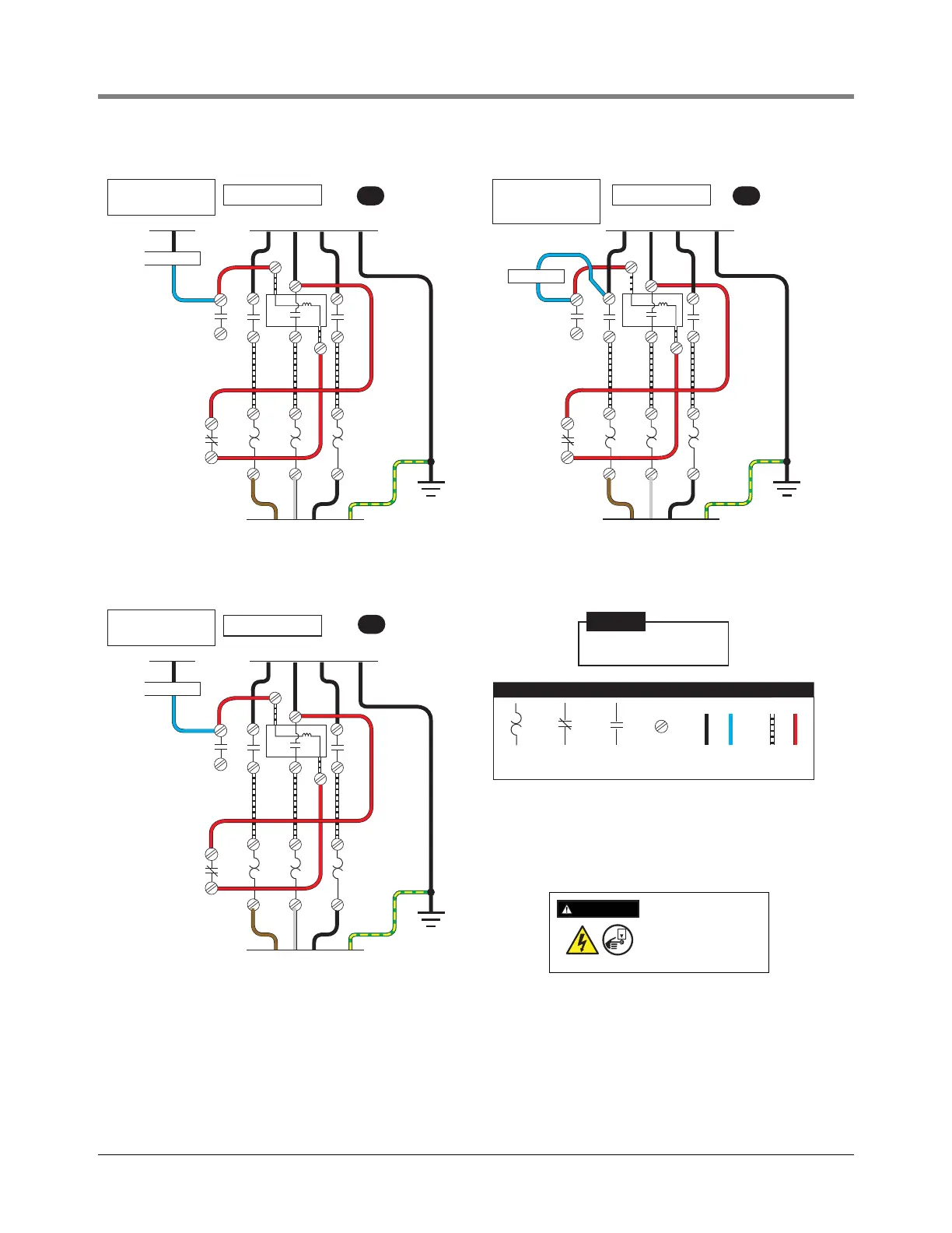
Figure 21. Three Phase Remote Control Box (Starter)
T1
L1
L1 L2NL3
L2
L3
T2 T3
To 208/240 V Supply
120 V Coil
COIL
2
9
3
Dispenser
3 Ambient
Compensated
Heaters
Connect To
Electrical
Ground
Brown Grey Black
To UMP
UMP: DP200U4 410852-005
STARTER: 410648-001
HEATERS: (3X) 410649-010
UMP: DP200U4 410852-005
STARTER: 410648-002
HEATERS: (3X) 410649-010
T1
L1
L1 L2 L3
L2
L3
T2 T3
To 208/240 V Supply
240 V Coil
COIL
2
9
3
Dispenser
3 Ambient
Compensated
Heaters
Connect To
Electrical
Ground
Brown Grey Black
To UMP
NOTE: Starter is wired to
208/240V to pump motor,
120 V to dispenser switch.
NOTE: Starter is wired to
208/240V to pump motor,
208/240 V to dispenser
switch.
T1
L1
L1 L2NL3
L2
L3
T2 T3
To 380/415 V Supply
240 V Coil
COIL
2
9
3
Dispenser
3 Ambient
Compensated
Heaters
Connect To
Electrical
Ground
Brown Grey Black
To UMP
UMP: DP200U4 410852-004
STARTER: 410648-002
HEATERS: (3X) 410649-003
NOTE: Starter is wired to
2380/415V to pump motor,
240 V to dispenser switch.
LEGEND
Overload
heater
Normally
closed
contact
Normally
open
contact
Screw
terminal
Wire added
by installer
Wire added
by manufacturer
oror
The enclosure is rated NEMA 1 and is to be installed only in a non-hazardous
indoor location. Use 75°C copper conductors only. Torque terminals to 20 Lb-in.
Refer to installation manual 577014-045 provided with the starter.
Refer to diagram A, B or C for appropriate wiring for the installation require-
ments.
Make ground connection in
accordance with local codes.
NOTICE
A B
C
DISCONNECT, LOCK OUT,
AND TAG POWER AT THE
POWER PANEL BEFORE
WIRING THE PUMP.
WARNING
OFF