INSTALL THE REDVOLT XL MODULE
The REDVOLT XL Module is designed with a reversible switch plate, enabling direct installation to the EPIC/SCARLET
BRAIN or mounting to other modules.
For more information on installing and removing the REDVOLT XL Module, go to:
"EPIC/SCARLET Adaptor Operations" on page29.
"EPIC/SCARLET Power Module Operations" on page31.
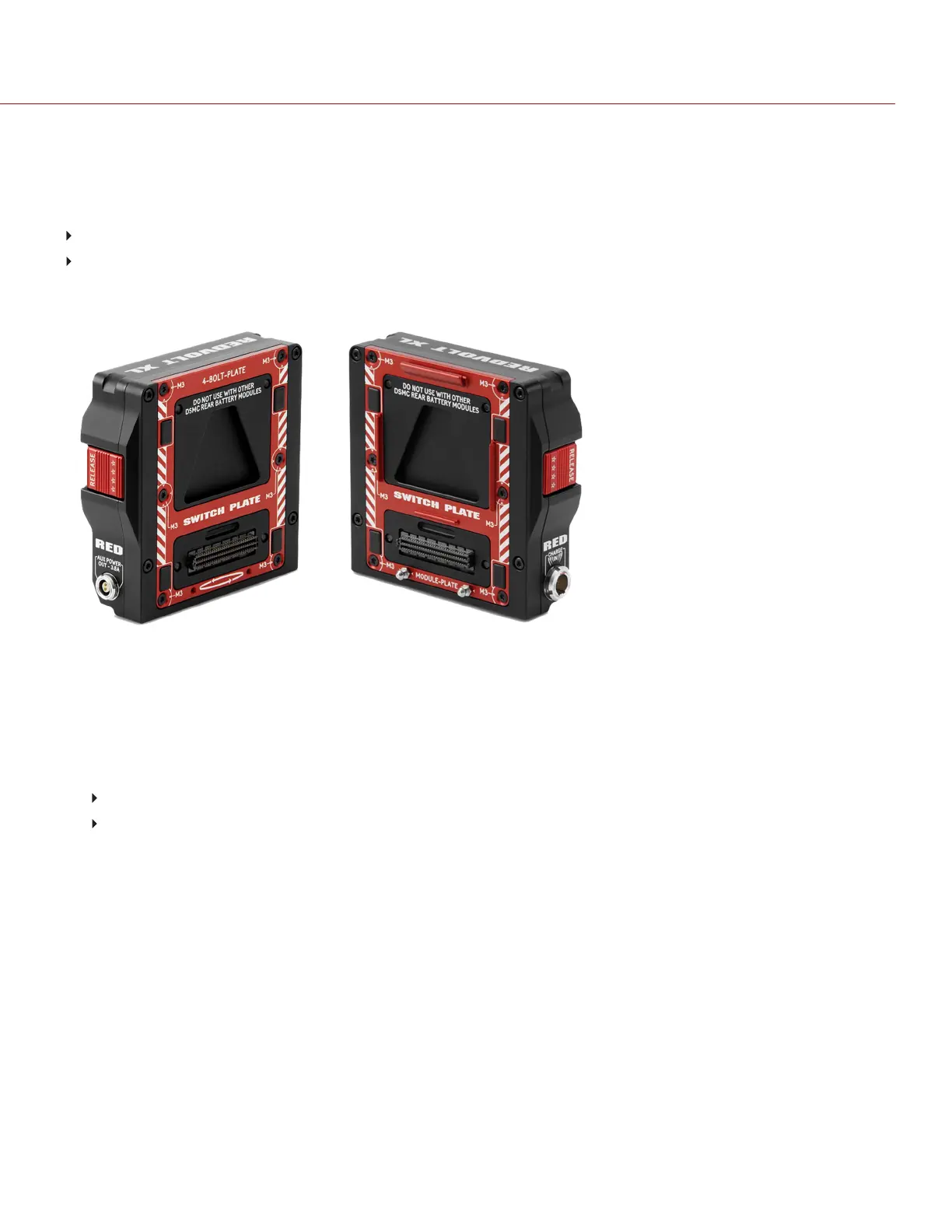
REDVOLT XL MODULE SWITCH PLATE
Figure: REDVOLT XL Module Switch Plate
To configure the switch plate for different mounting variations, follow the instructions below:
1. Loosen the six (6) M3x0.5 x 8 mm screws attaching the SWITCH PLATE evenly using a T10 TORX driver.
2. Remove the six (6) screws. DO NOT discard screws.
3. Install the switch plate to the desired mounting configuration:
4-BOLT-PLATE (Left image): Supports attachment directly to the BRAIN.
MODULE PLATE (Right Image): Supports attachment to DSMC modules.
4. Insert and tighten the six (6) M3x0.5 x 8 mm screws evenly. DO NOT FULLY TIGHTEN.
5. Fully tighten the six (6) M3x0.5 x 8 mm screws evenly. DO NOT exceed 70 in-oz, or damage may occur.
WARNING: DO NOT OVERTIGHTEN.
For more information, see the REDVOLTXLModule Installation Video, availabe at
www.red.com/store/products/redvolt-xl-module.
NOTE: For more information or replacement screws, please contact your Bomb Squad representative.
C OPYRI G HT © 2017 RED.C OM , LLC 955- 0038, REV-AD| 40
RED DSMC POWER OPERATION GUIDE