11-01
680 High Clearance Sprayer - Connection & Startup
Section C
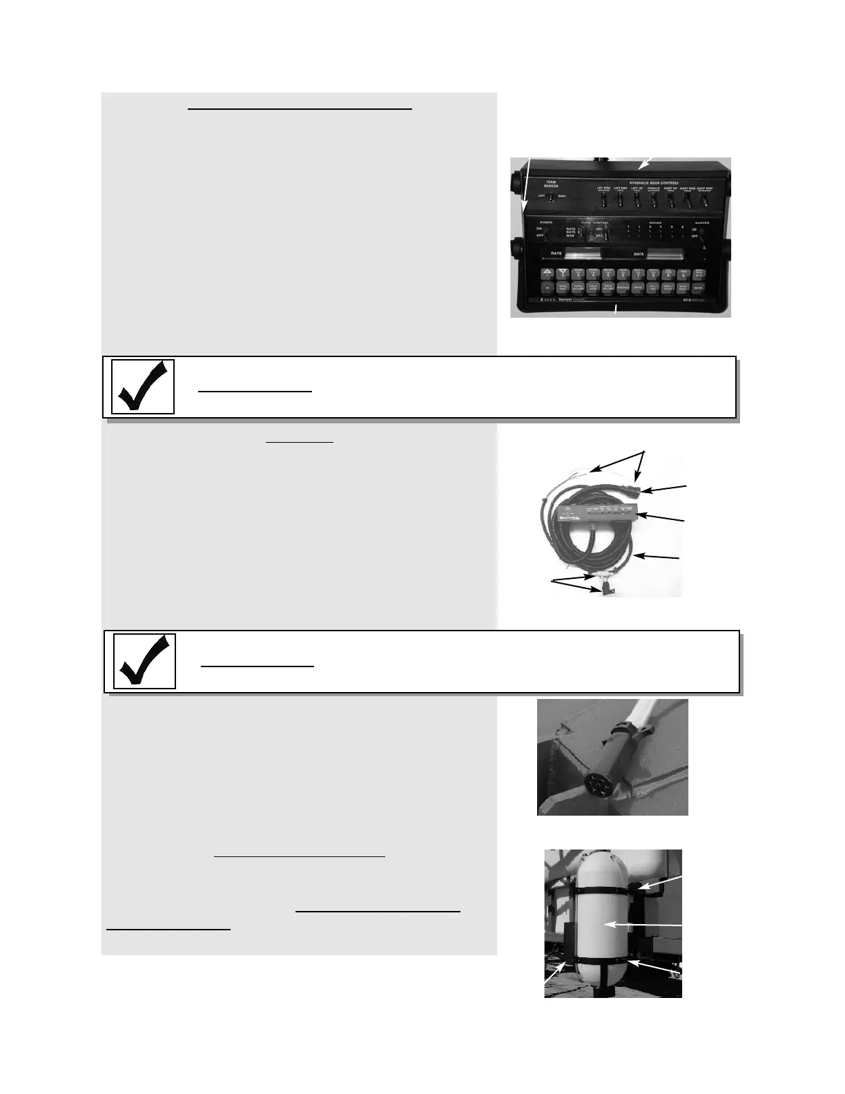
Solution Spray Control System
The solution spray control console should be installed in
the cab, and the wire harness routed to the back of the
tractor per installation instructions provided by the control
manufacturer.
Install the speed sensor or radar (if necessary) and con-
nect them to the solution controller according to the
speed sensor, radar and solution controller manufactur-
er’s instructions. For tractors with radar systems built in,
interface cables are available from your Redball
®
Dealer.
Calibrate the speed sensor or radar according to the
manufacturer’s instructions or the instructions provided
with the solution controller.
Electrical
Besides the control system, boom fold control switches
need to be wired into the cab. A power source of 12V
DC and a chassis ground is required for this panel.
1. Route the controller power cables to a power source in
your tractor capable of at least 15 AMPs.
• White is Negative (-)
• Red is Positive (+)
2. Route the harness out of the cab down to the hitch
area. Connect the harness from the control box to the
harness on the sprayer.
Light System Seven Pin Connector
The connector provides the signal from the tractor to the
sprayer’s light system. Connect the seven-pin male con-
nector to the tractors seven-pin female connector at the
rear of the tractor. The connector for the sprayer is locat-
ed near the hitch. If the tractor is not equipped with such
a connector, see your tractor dealer.
Foam Marker (Optional)
If not already done, attach the foam marker tank and
compressor assembly to the frame of the sprayer. Refer
to Redball
®
Manual L-20095 Foam Marker Parts and
Operator's Manual for specific installation and setup
instructions.
8
Section C
DO NOT remove the fuse or fuse holder from this power
source. These are for the protection of these components
and removal will void the warranty.
IMPORTANT
DO NOT remove the fuse or fuse holder from this power
source. These are for the protection of these components
and removal will void the warranty.
IMPORTANT
Foam Marker Mounting Position
Right Front View
Tank
Compressor
Assembly
Frame
Mount
Tank
Mount
Raven Solution Spray Controller (optional)
Directional Stack Controller
Brackets
Seven Pin Connector
located near the hitch
Directional Stack Control Box
Harness
Connector
Control
Box
Power Connections
Fuse
Holders
Harness